 willbaden
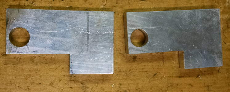
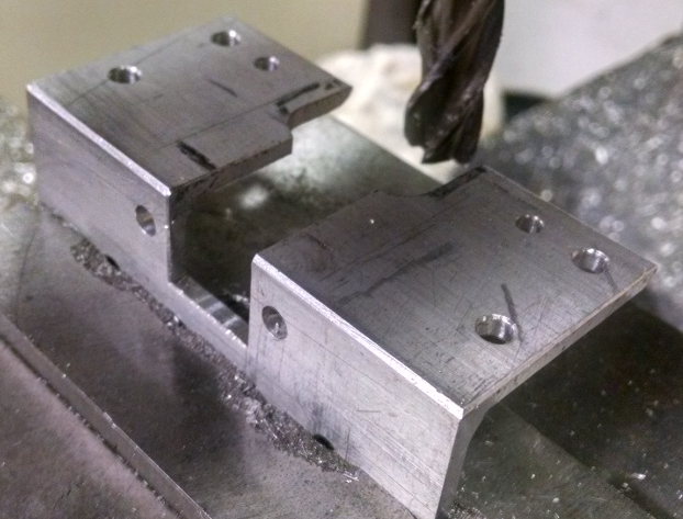
Now that the upper guide is mounted, the lower guide and upper bearings can be added. The lower guide is mounted with a couple of aluminum pcs. These mounts were bored out for a snug with with the lower guide:
The mounts were then relieved to allow for the belt to pass under. This allows the mounts to attach on the upper part.
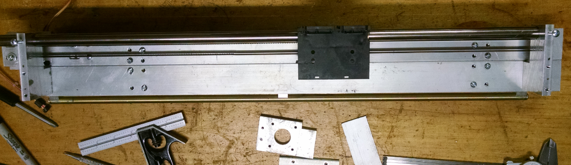
These were then mounted to the x axis. The lower guide was ran through the holes and fastened using screws to fasten them.
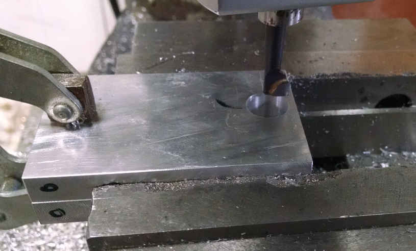
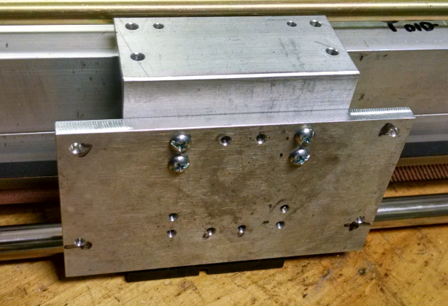
Next the plate that mounts to the old printer ink carriage was made. This will connect the upper right angle bracket to the old printer ink carriage. The holes were center drilled in the mill/drill and then opened up using a drill press.
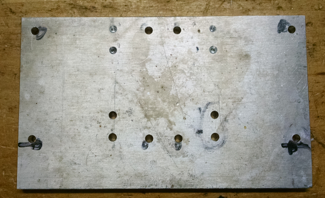
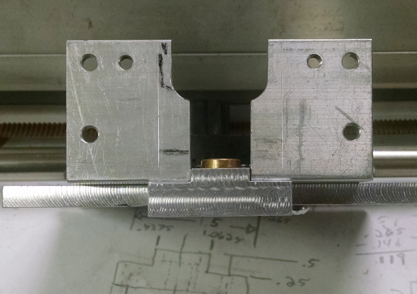
The plate was mounted with the upper aluminum right angle. This was mocked up using some clamps to hold it in place and get measurements for the bearings that will be used.
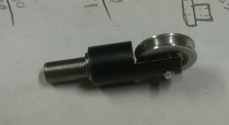
One of the bearings will be movable to allow for any irregularities of the upper shaft to be absorbed. This will use a plunger style of action, but will need to be kept from rotating around the plunger axially. The tension will be kept with a spring that was found in the parts bin from old copy machines and printers.
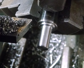
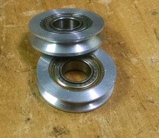
The bearings were made to have v grooves machined into them to capture the upper guide. The outer section was made from aluminum and were pressed onto the bearings.
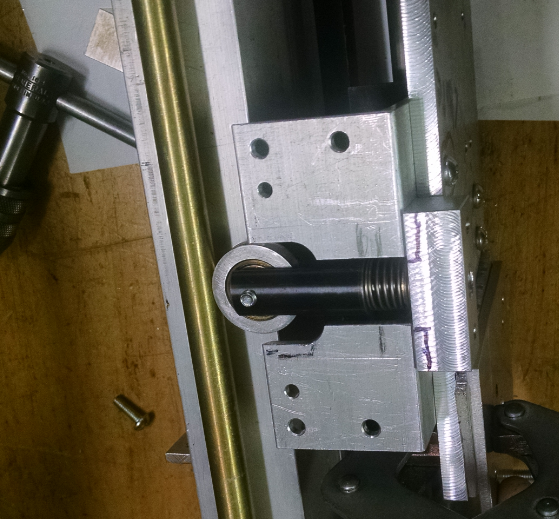
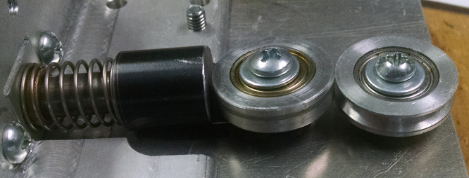
Here is a picture of the plunger with the v groove bearing installed:
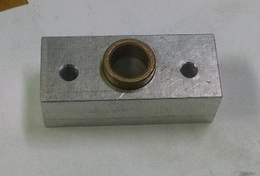
The movable bearing needed to rest in a bushing block. This was a small piece that had two mount holes on the outside and a center counterbored hole that the bushing was pressed into.
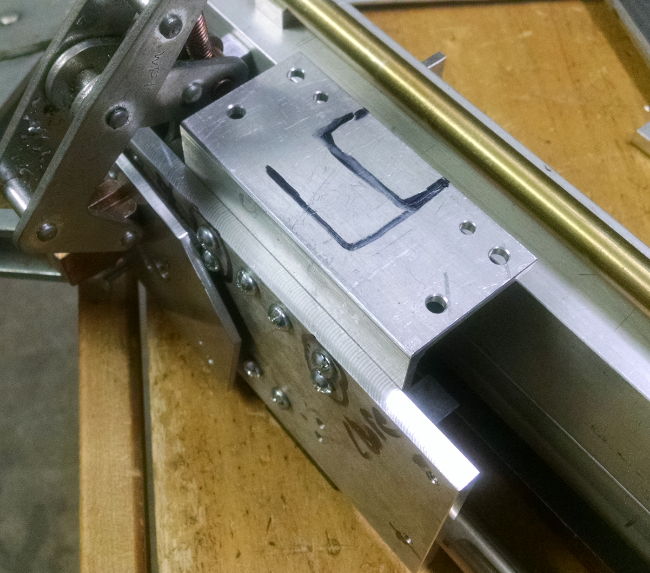
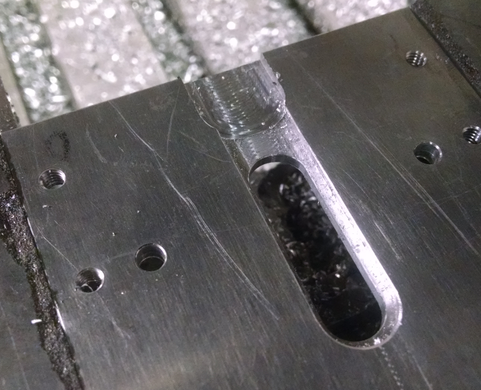
Mounting the bushing block and allowing the plunger to be mounted, the upper right angle needed to have relief slot cut into it:
Mocking up the parts that were made showed that the bushing block needed some relief to allow for more tension on the spring that was used.
To mount the rigid bearing, a flat plate with a slot was made. The slot will be used to keep the plunger aligned, preventing it from rotating. The relief allows for the plunger to move back and forth freely.
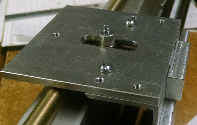
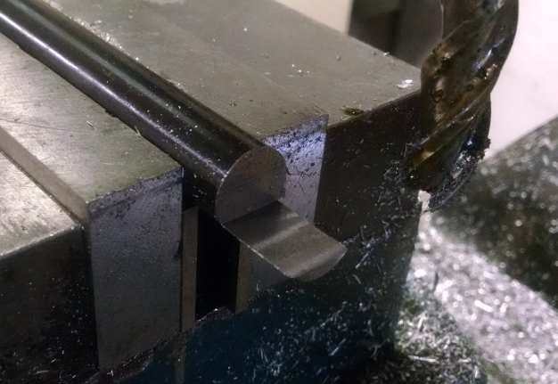
Here is an assembly view of the plunger riding against the solid bearing. The upper guide rides between these.
With it all assembled, the x axis carriage moves back and forth freely. Hopefully with the weight of extruders on the front, the rigid bearing will maintain contact with the upper guide. Now to mount the x axis to the z axis movement. . .
Discussions
Become a Hackaday.io Member
Create an account to leave a comment. Already have an account? Log In.