 RasmusB
I have made some progress on the keyboard controller since the last log entry.
As we learned last time, our USB keyboard will need to send a specific scancode for each button pressed. All other logic (interpreting the keypresses) is done on the computer side. So we don't really need to bother with which scancodes we are sending, since we can remap everything on the host side anyway.
Other people have used that approach. I tried out a Linux port for the Psion called 'Kludged Linux' and dumped the keymap. The author has just used his own scancodes and mapped them to the correct keys in the keymap. This is perfectly fine for that application, since the keybord will always be connected to the same hardware in the same way. In that case, you can use whatever scancodes you like.
In my case, I'm building an USB keyboard. Even though I'm only planning to use it for this project, it would be nice to keep it as Plug 'n Play as possible. That means that I will use the standard USB scancodes as far as possible, so I can plug it into any computer for testing and prototyping without a custom keymap. I still haven't decided on the main hardware for the project, so an USB keyboard also allows for the most flexibility on that end as well.
So I made a spreadsheet with the following (from left to right):
- USB Scancode
- Kepmap keycode in hex and decimal (just for convenience)
- Row and Col (keyboard hardware mapping)
- What is printed on the keys:
- Primary key function (without modifier keys)
- Secondary function (Shift key pressed)
- Tertiary function (AltGr pressed)
- Matching each combination of modifier keys to the keymap names and format (see man keymap)
Using this, the next step was to write the firmware for my microcontroller. For convenience, I'm using an Arduino-compatible board, Olimexino-32u4. The Arduino IDE had a working example on how to implement a keyboard device and serial port on the same USB connection. (It's really easy)
I actually started out using just the serial connection to debug my code. If I had made a stupid mistake somewhere, I really din't want my first keyboard to spew weird stuff onto my screen and possibly have something nasty happen (like by mistake sending Ctrl+A, Delete and Ctrl+S or similar...). This allowed me to safely test my matrix scanning code with serial debug messages before implementing the 'real' keyboard code.
The current version (1.6) of Ardunio IDE doesn't support sending raw scancodes. Instead, it allows you to send printable ASCII characters and modifier keys. This will no doubt be enough for 95% of USB keyboard implementations, but for me it would add unnecessary overhead to my code (keeping track of what counts as a modifier key and not). Instead, I found a patch that introduces proper scancode functionality, and that seems to work very well!
The code is very straight forward and does not require any additional electronics but the keyboard itself.
- First of all, all pins are set to Inputs. This makes them high-impedance.
- The internal pull-up resistors are enabled on the column pins. This turns them logic HIGH.
- Then, one row at a time is turned to an output and driven low.
- Check the status on the column pins. A logic LOW signal means that column is connected to the active row because that key is pressed.
- When the matrix is scanned, it is compared to the last known state. Then we send 'pressed' scancodes for the newly pressed keys, and 'released' scancodes for the keys that has been released.
- Repeat from step 3.
After using the serial port to nail down the last typos in my matrix scanning code, I felt confident enough to try it out! Since I haven't got my adapter for the real Psion keyboard yet, I had to improvise (sorry for the crappy shot):
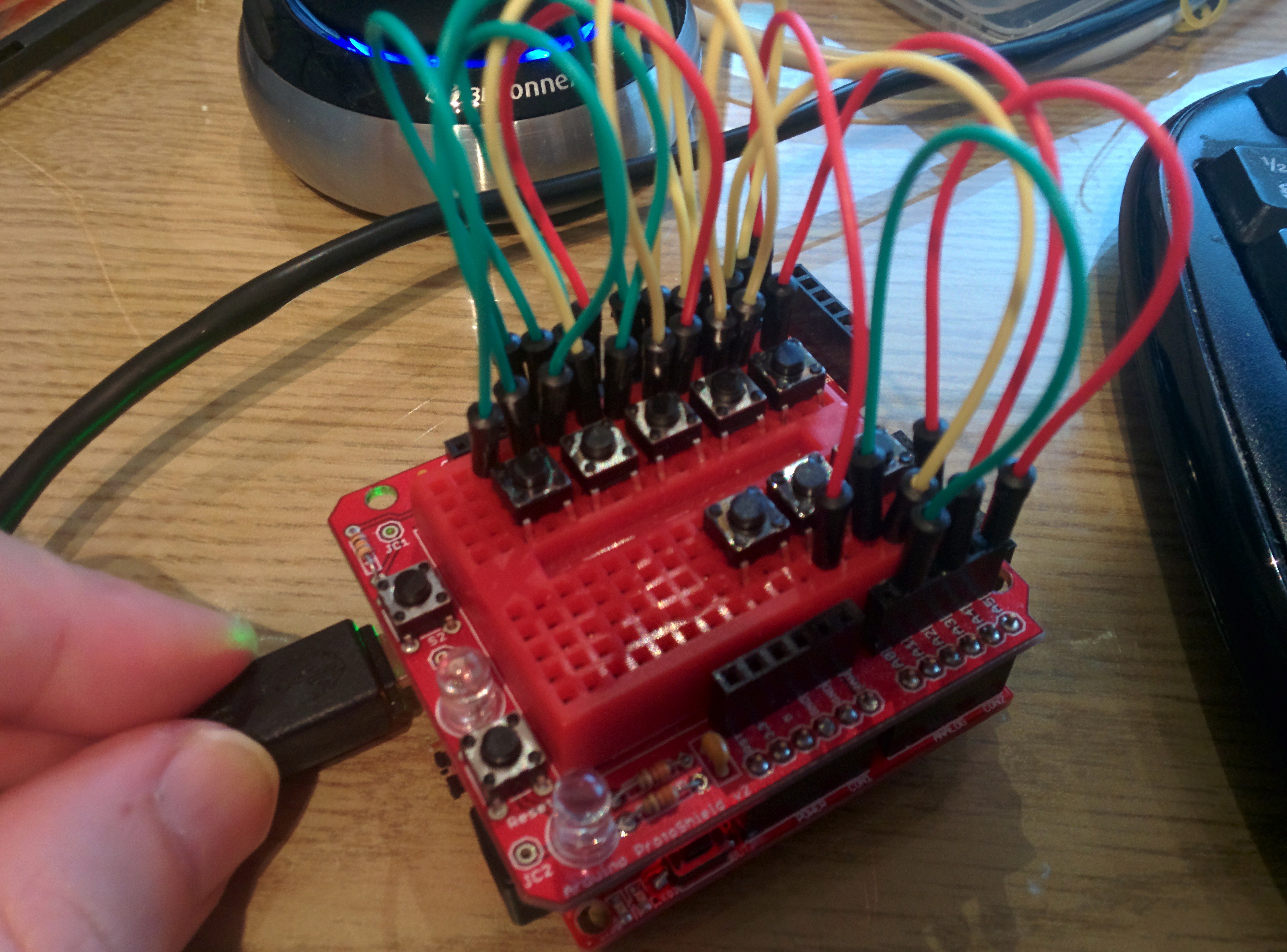
As you can see, no other hardware than the buttons themselves are used. I did have to cut a few bridges on the Olimex board to get decent voltage levels since the internal pull-ups are very weak, but that won't be an issue when I do this for real.
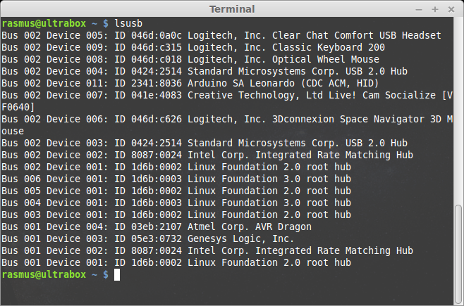
On the USB bus, the 'keyboard' identifies itself as an "Arduino SA Leonardo" running two device profiles: CDC ACM for the serial port, and HID for the keyboard part.
Anyway, this worked beautifully! I honestly didn't expect this to work as well as it did, considering how simple the code is. But the keys work exactly as you would expect them to on a proper keyboard - keep them pressed and they will repeat at a reasonable rate. Press the shift key and you get a capital letter, and so on. I even tried connecting it to my Raspberry, and it worked perfectly there as well.
The next step is to strip this down. I will make my own custom PCB with just the absolute necessities: the ATmega32u4, a USB connector and a keyboard connector. In its final incarnation, the keyboard controller will live as an integrated component on the main PCB. Before I get that far I want to be sure that I know how to wire the uC up so I don't make any silly mistakes on the more expensive board.
Discussions
Become a Hackaday.io Member
Create an account to leave a comment. Already have an account? Log In.
Have you considered using a Teensy to drive the keyboard? I suspect that your solution of making an own controller board is more elegant though.
Are you sure? yes | no
Yes, that would be perfectly possible. I think the Teensy 2.0 also uses the ATmega32u4 so my Arduino skectch would work as-is on that.
Anyway, the bootloader that the Teensy uses is not open sourced AFAIK, so that would make it a bit more tricky to include on my main board further on. The Arduino Leonardo bootloader is open sourced, so it is a lot easier to clone. I guess one could make the argument "but the teensy is so small, just include the whole board", but I prefer not counting the chickens before they hatch :) For now, I'm assuming everything will be a very tight fit so I'm saving space wherever possible.
Are you sure? yes | no