 RasmusB
I have been able to spend a few hours on the project, and I thought I could share some of the progress so far.
I was going crazy trying to figure out a solution to the screen and processor dilemma. I still haven't figured out a perfect solution, but I choose to focus on other parts in the meantime.
One problem with upgrading a small, handheld device is that there are serious space constraints you have to work around. Finding out how much room (or rather how little room!) I have to work with inside the empty shell is very time consuming, but spending the time now makes things a lot easier later on.
I have two goals with the mechanical design:
- Everything must fit inside the original enclosure
- Reuse as many mechanical features as possible (pushbuttons, battery compartment, connectors etc.)
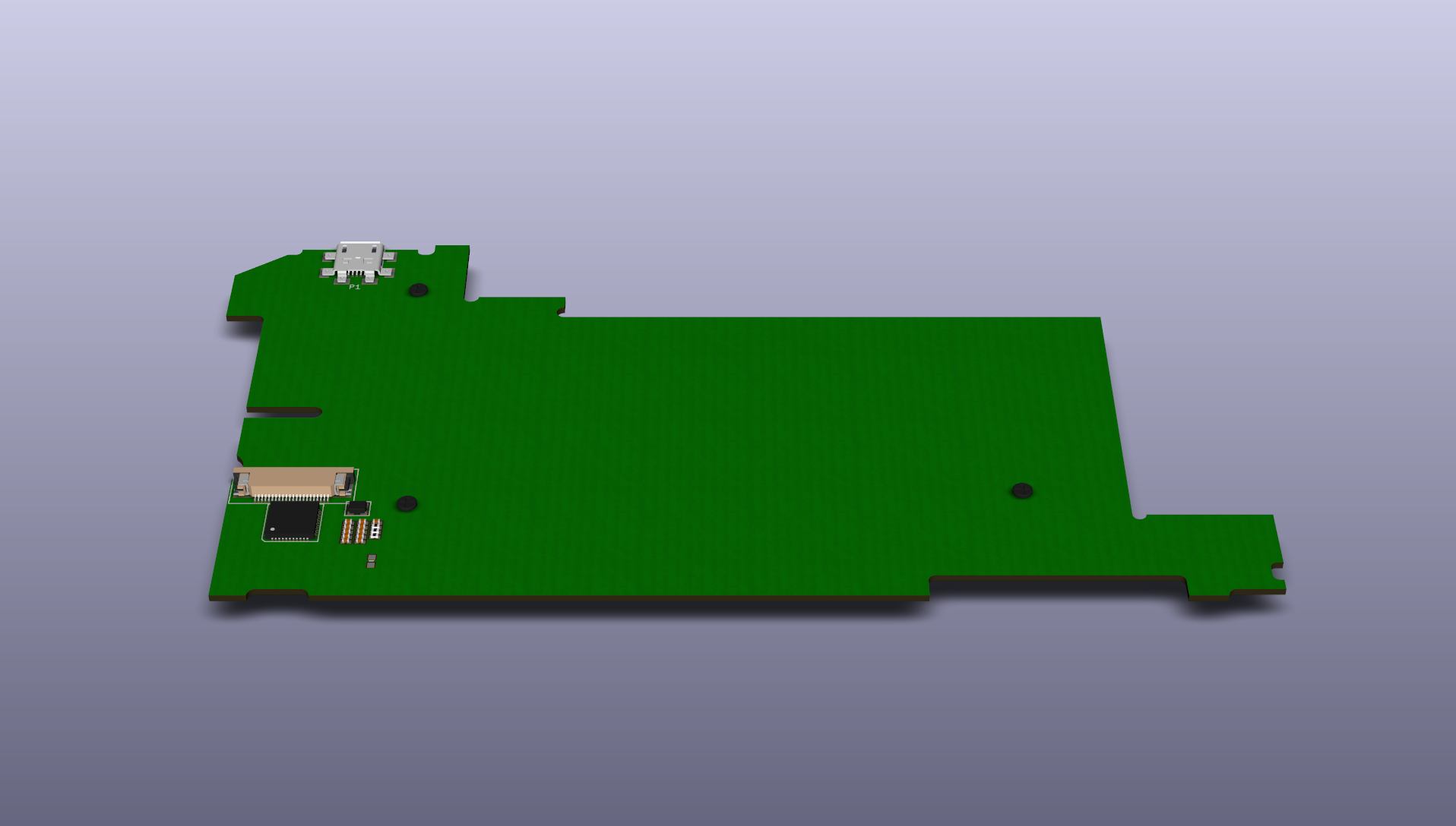
The easiest route towards these goals is to start out from what I already have, in my case that is a main board from one of my Psions that wouldn't boot. (Bonus points to anyone who can spot the problem, it's actually visible in the photo below)
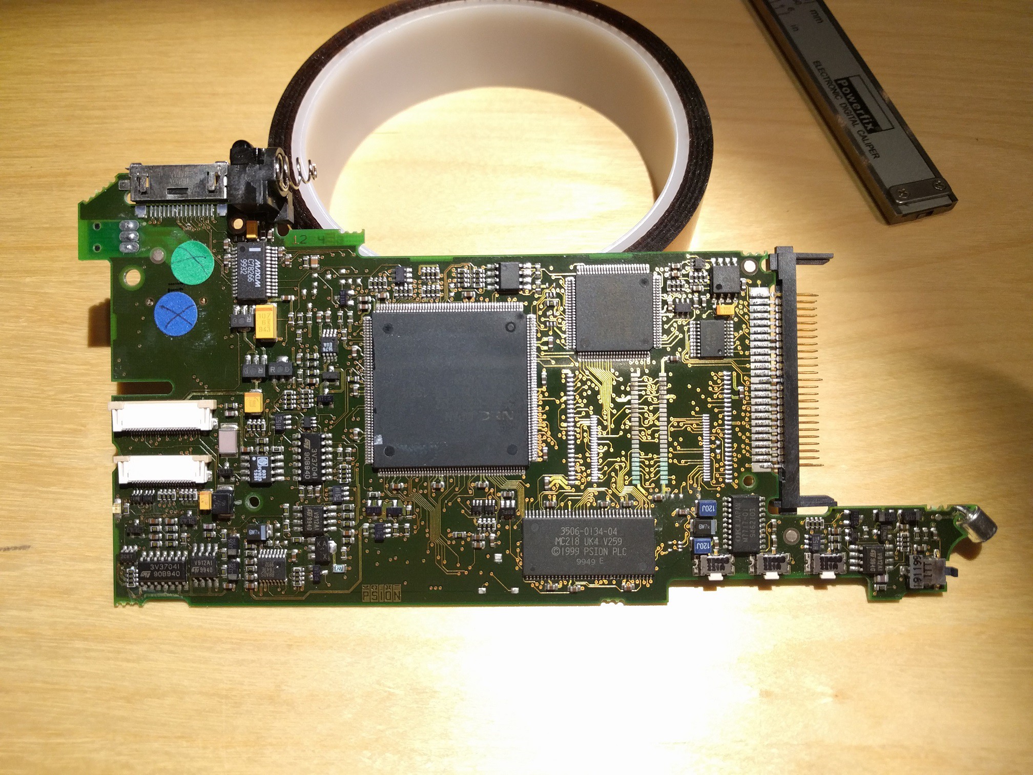
For my first attempt, I used my digital calipers to measure the outline of the board. While this worked OK for the most part, i ran into some trouble.
- I wanted to reuse components like the battery spring, but the spring holder was obscuring how it mounts to the PCB
- It was very difficult to accurately measure the location of the mounting holes since they are closer to the middle of the PCB, making it too easy to take crooked measurements
- The most complex shape (the lower right part in the picture) was very difficult to measure accurately, and that is the area with I have the least space to spare.
So I decided to take a more refined approach. I assaulted the PCB with my hot air soldering tools until only the board itself was left:
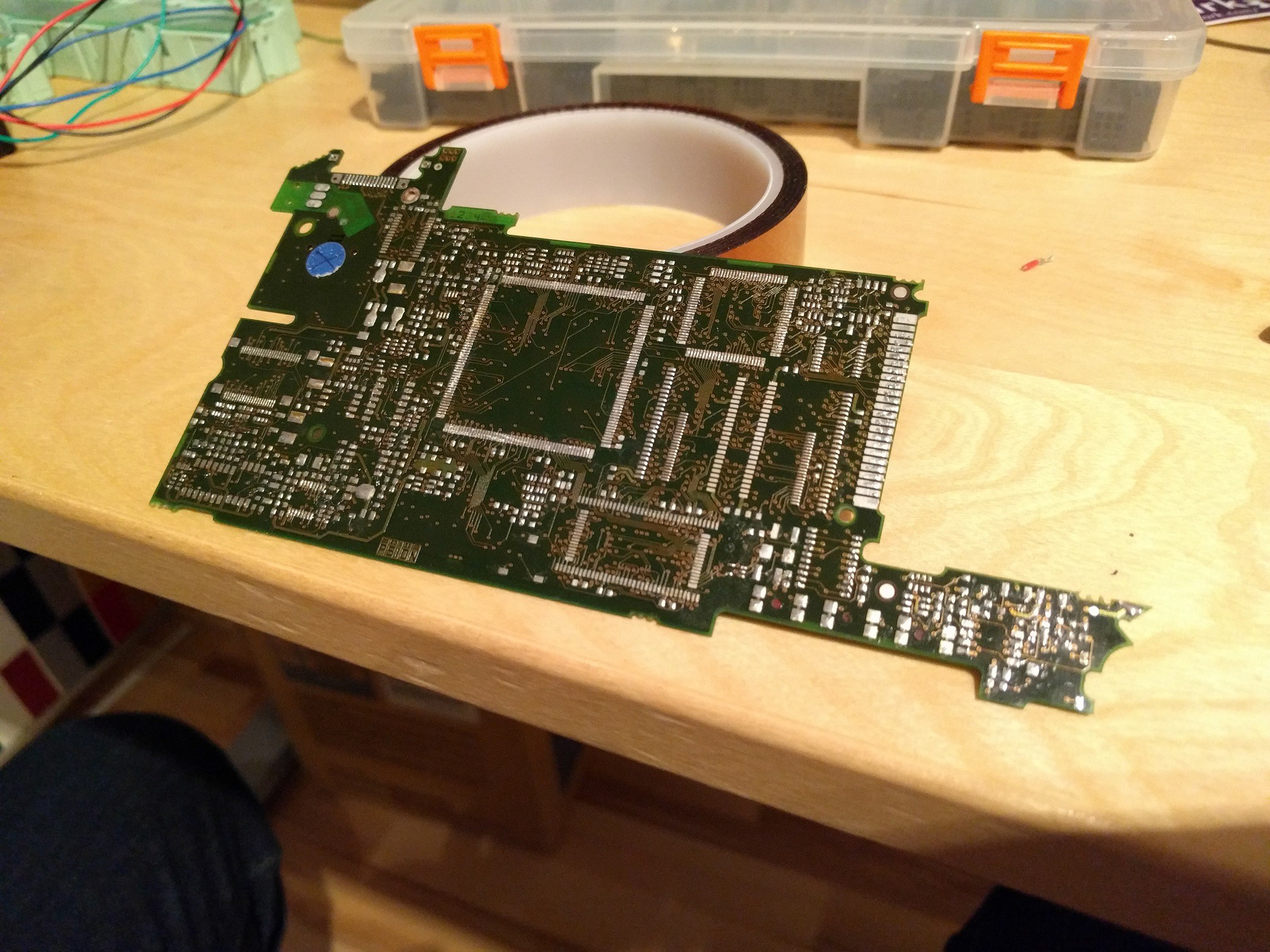
I had planned to harvest some components that I want to reuse for my own PCB from this board anyway. Now that the PCB was flat again, I could use a flatbed scanner to digitize the board.
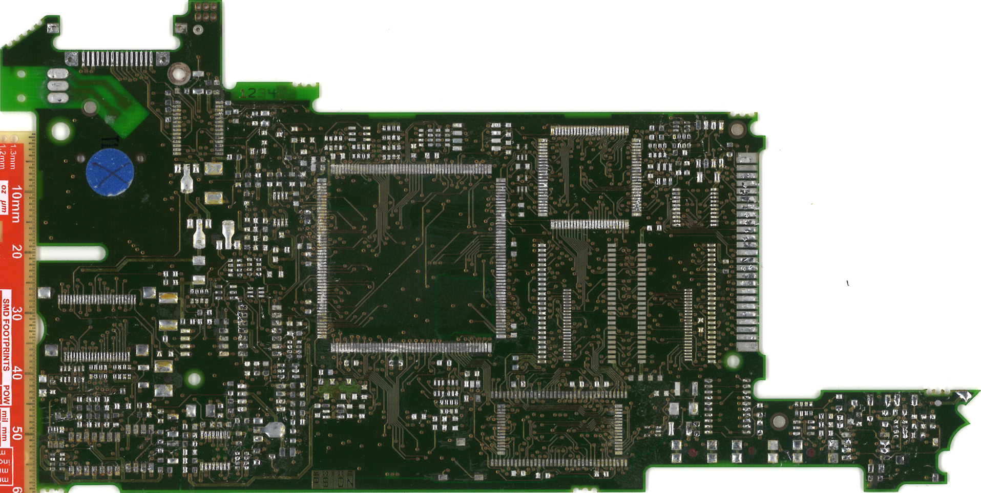
With my scanned image trimmed down to the very edges of the PCB, it was only a matter of importing the image in FreeCAD and drawing the outline on top of the image.

To verify that I got the outline correct, I printed the outline on my laser printer and laid the PCB on top. To my surprise, it almost, kinda matched. I measured my printout carefully and concluded that printing something in 1:1 scale on my printer actually made it just a tiny bit to small. Once I had figured that out, I could adjust the scale and print it again. But it still looked off! What was going on?
After spending more than an hour backtracking all my work so far and taking lots of careful reference measurements from the actual PCB and comparing them to my printouts and CAD model, I realized what went wrong - the scanned image has a small difference in scale between the vertical and horizontal axis!
I thought I was being clever when I included a ruler in my scan, but it turns out the proper thing to do would have been to place another ruler in the horizontal direction as well to verify that the scale was the same in both directions. I also realized that I had been bitten by this behavior from a scanner before, but apparently I didn't get bit hard enough that time since i forgot about it...
Now that I knew what the problem was, it was easily fixed by adjusting the size of my reference picture in FreeCAD and tweaking my drawing. Now the printout and the PCB matched perfectly!
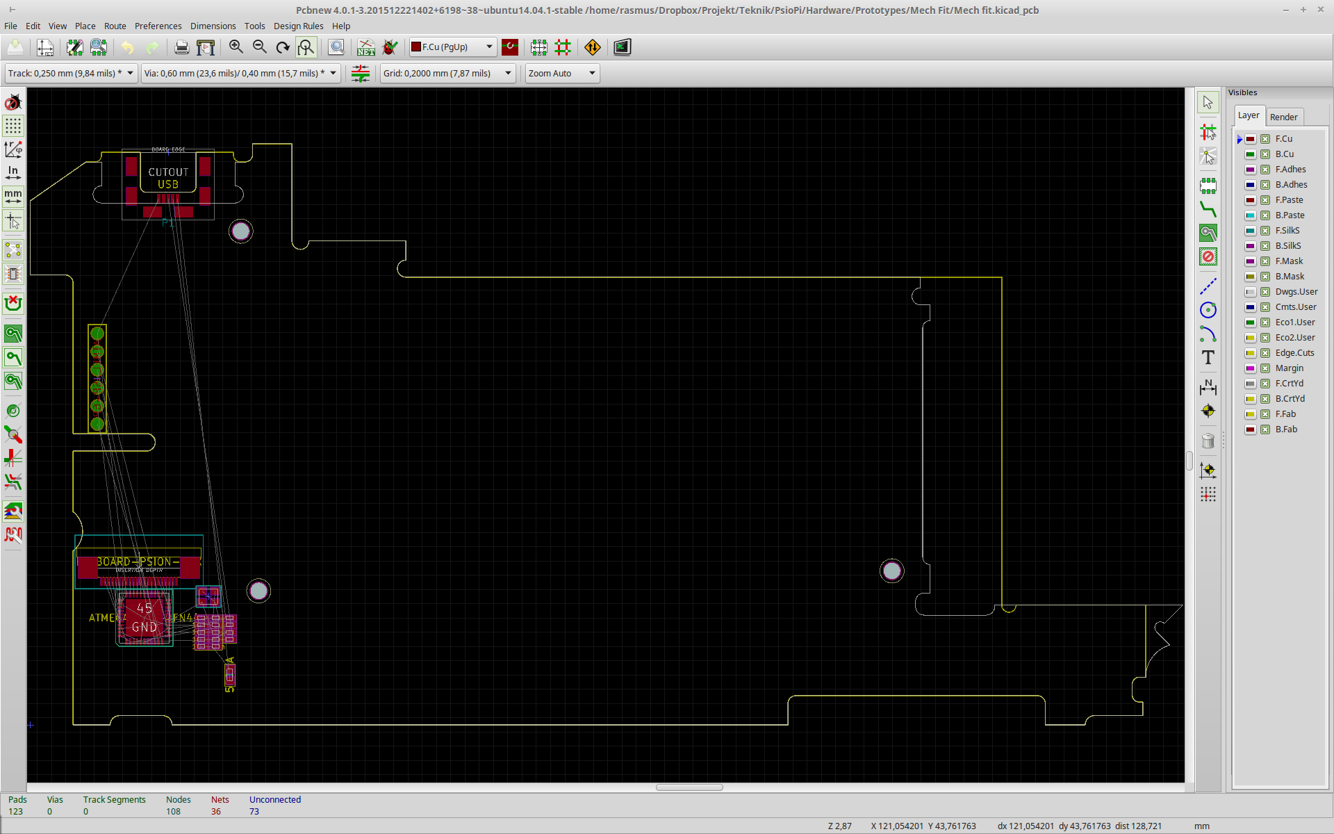
Getting the outline into KiCad
The next step is to get my freshly drawn outline into KiCad. From FreeCAD I exported my sketch as an "Autodesk DXF", since KiCad can import DXF. Unfortunately, KiCad doesn't support all features of the file format so not everything is included in the import. To get around this, import your DXF into LibreCAD (or other software with complete DXF support), select everything and use the "Block / Explode" feature. Save the DXF, and now you can import it in the footprint editor.
The next step
 Right now I'm using my outline to create a board that fits perfectly into the Psion shell. It looks a bit empty still, but I'm planning to include the following features:
- My USB keyboard controller for the Psion keyboard
- USB micro connector where the original serial port used to be
- Charging port / barrel jack
- AVR ISP connector accessible through the Psion debug port
- Battery spring connector for main batteries
- Battery /speaker flex connector for main batteries
- Battery spring connectors for backup / RTC battery
- Lid open / closed switch
- Voice recorder button switches
- Compact Flash slot cover open / closed switch
- Indicator LEDs
... and that's about it! The end result will look and feel like an original Psion, but in practice it will just be a very over-engineered keyboard since it won't do anything unless it is connected to a computer. But I'm getting closer! Once I get this working, I'll have a much better idea of how much room I have to work with, and I can start thinking about what CPU I should use again.
I'll keep you posted with the progress. Happy hacking! :)
Discussions
Become a Hackaday.io Member
Create an account to leave a comment. Already have an account? Log In.
Hello, awesome project. I use everyday to take notes and write ideas on the go a classic HP 200LX + 256MB CF Card to exchange files. I got some broken HP 200LXs devices from a store, that I use to repair my main device, but I'm planning to put my spare RPi, modded to be flat (I pulled of the USB ports, Ethernet, HDMI, GPIO pins) and low profile. I built a portable RPi also, but the core temp is a problem to carry the device into the pocket.
I saw you're hunting for a best fit lcd replacement for the old psion one, to be used into RPi. It's the same case of me, the vintage sharp LCD from my HP 200LX has almost the same size of Psion one (Yes I have a broken psion also), I'd like to use it with the RPi to get the low power consumption target. The contrast is fine when you use it outdoor, since the DOS programs are almost characters only, but I'm afraid spending a time to debug and reverse engeneering and 20 year old LCD =(. But I didn't find any similar one!
So, I'm trying to finding the most similar one...
Keep this good project!!!!
Regards
Are you sure? yes | no
Excellent! :D Yes, these devices are great. Lasts forever :)
Will yo make a project log to document your build?
Are you sure? yes | no
Maybe someday, I have some uploaded videos with my RPi builds, but none explaining step by step about the construction. In fact, I'm a bit upset with RPi because it's heat. If I put it into a compact closure, It gets really hot even if a try to underclock it, so I couldnt glue the RPi board with a small battery to get more compact. =( ....
Are you sure? yes | no
Freescale, (pardon NXP now), has a pretty small SoM called SCM-i.MX6D:
http://www.nxp.com/products/single-chip-modules/single-chip-module-i.mx-6d:SCM-i.MX6D
It integrates the CPU, the memory and the boot flash. Using a similar device the most of the high speed design can be "outsourced" to keep your baseboard simple.
I am wondering if there is a similar sized TFT out in the market.
Are you sure? yes | no
Thank you for the tip! Using that does remove some of the complexity, but on the other hand the baseboard wouldn't be that simple anyway. The package uses 500 0.65mm BGA solder joints, and making a fanout for that would require a pretty expensive PCB - maybe 8-10 layers, 0.1mm traces and spacing.
But I'll keep my eyes open to see if they make an evaluation SOM or similar :)
Are you sure? yes | no
I registered just to comment, like everyone here.
Been toying with the idea of getting a Psion 5MX and putting in a Pi Zero myself - without taking your step of putting in your own PCB :)
Will be following your build log and see how I can be inspired by it.
I wonder if a naked Intel computestick would work instead of a raspberry Pi? Or any of those Android-based TV stick?
Are you sure? yes | no
Great idea :) Make sure to start a build log of your own for your project, it is always interesting to see other approaches.
The biggest hurdle for me has been to find a usable screen. If you are going for a compute stick or RPi, I would suggest to look for a HDMI screen that fits in the 5mx case.
Are you sure? yes | no
Just paid for a whopping three different psion devices on ebay, so will have to wait for them to arrive and see what is the status of the items. Did some digital prototyping for the display - can you check what is the total screen area? Including the silk-screened buttons? Someone on the RaspPi forum said it's 145 x 60mm. If that is the case, only the 4 inch GPIO screen will fit perfectly: http://www.aliexpress.com/item/Raspberry-Pi-4-inch-IPS-touch-screen480-x-320-Pixel-Can-work-for-raspberry-Pi-B/32336186474.html
Have to wait for the Rasp Pi Zero to be available though - it's still out of stock everywhere. In the meantime, gonna see what I can find out about the stuff to, well, stuff in the Psion anyhow.
Are you sure? yes | no
Yep, 145x60mm is correct.
Are you sure? yes | no
Psion 5MX rebooted - Time for a Kickstarter. That board is positively huge when you think how much *stuff* you can squeeze in to that much space these days. There's enough space for about 1 1/2 iPhones :¬)
Are you sure? yes | no
Yes, that would have been awesome :D
Are you sure? yes | no
Hi, great to see you
back on this road again :) I really love these devices and collected
throughout the years quite a lot of them. Send me a pm if you need
parts. I would be happy to contribute to this great project.
Are you sure? yes | no
Thank you, that's really generous of you! :)
Are you sure? yes | no
I think I can see why that board wouldn't boot. It seems to be missing a case, batteries, screen and keyboard. What do I win? ;-)
Seriously though, you seem to be putting some real effort into this and it looks really promising. Keep up the good work.
Are you sure? yes | no
Haha you win the opportunity to go back to the image and find yet another excuse for a Psion to refuse to boot ;)
Thanks, having people like you showing interest and commenting really helps with the motivation :)
Are you sure? yes | no
Well, to my very inexperienced eye, there seem to be a couple of things wrong with the board. The open/closed microswitch operated by the sliding keyboard is missing (but I can't imagine that would stop it booting) and there appears to be damage to the edge of the processor (but it could just be a bit of glue or something similar). Am I close?
Are you sure? yes | no
That is absolutely correct, the missing microswitch is keeping the machine from booting! When you close the lid, the Psion is supposed to enter sleep mode (it just keeps the RAM and RTC powered with a backup battery). When the switch is missing, it believes that the lid is always closed and refuses to start at all. :)
Are you sure? yes | no