 RasmusB
Hello world!
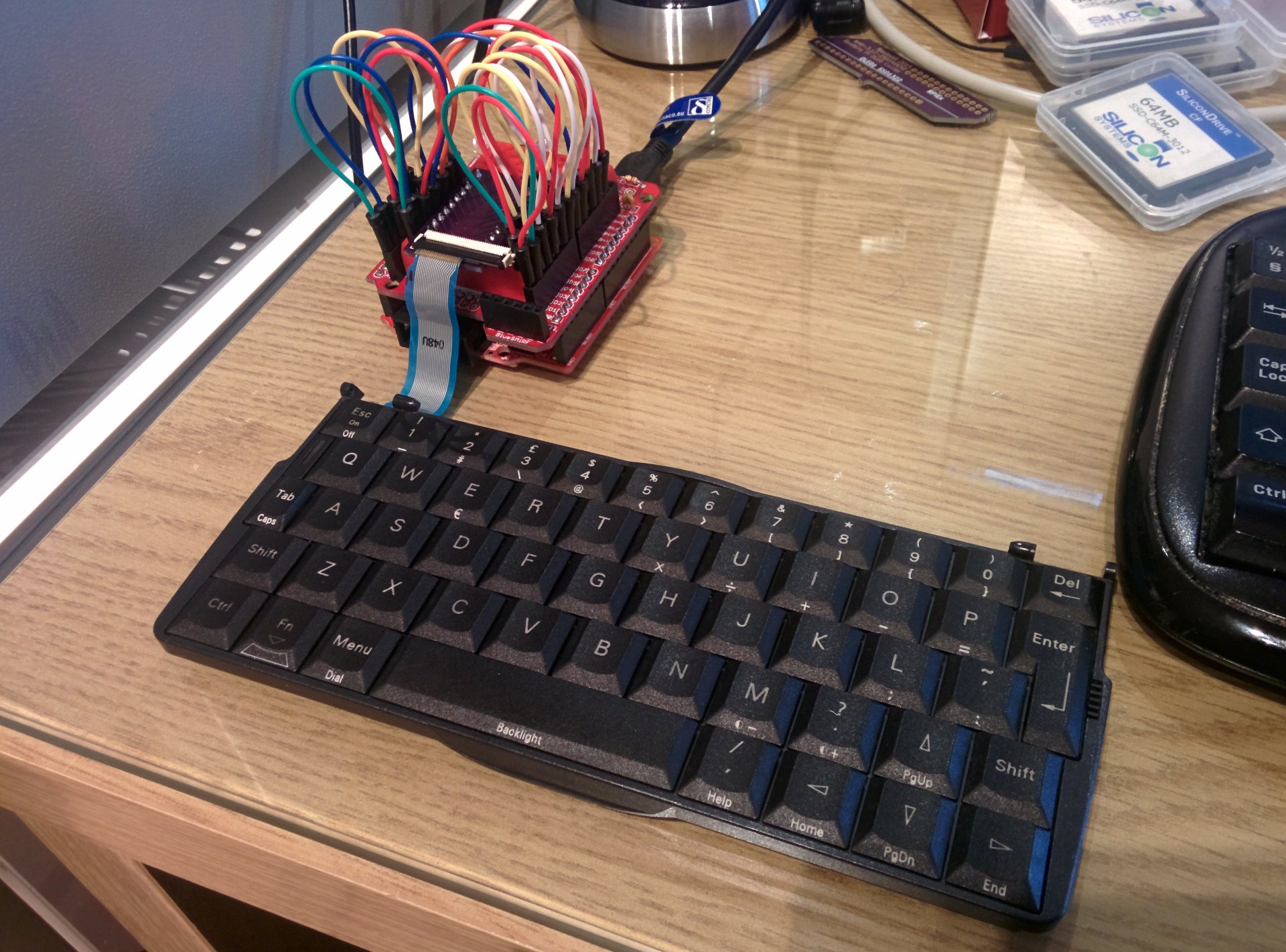
Of course, that was the first thing I typed into my new, beautiful keyboard. Now it is working perfectly, even though it looks a bit messy:
If you have a really good memory, you'll remember that the keyboard connector is on backorder for another five weeks or so. So what do you do if you don't have the correct connector? You fake one!
I digged around in my parts bins and found a similar connector. It was made for a 0.3mm thick FPC cable, and had the correct 0.5mm pitch. The only difference that mattered was that it had 30 pins instead of 22.
If you are ever faced with this situation, it is VERY tempting to solder the bigger connector centered on your original footprint, like this:

This is a terrible idea! If I had soldered the connector like this, I would not have had any control over the horizontal position of the cable in the connector. My 22 pin cable can end up being connected to ANY 22 pins between pin 1-30. Or even worse, somehow ending up in some weird middle position where none of my pins are connected. It's a nightmare, trust me.
The smarter way is to solder it like this, offset to one side:
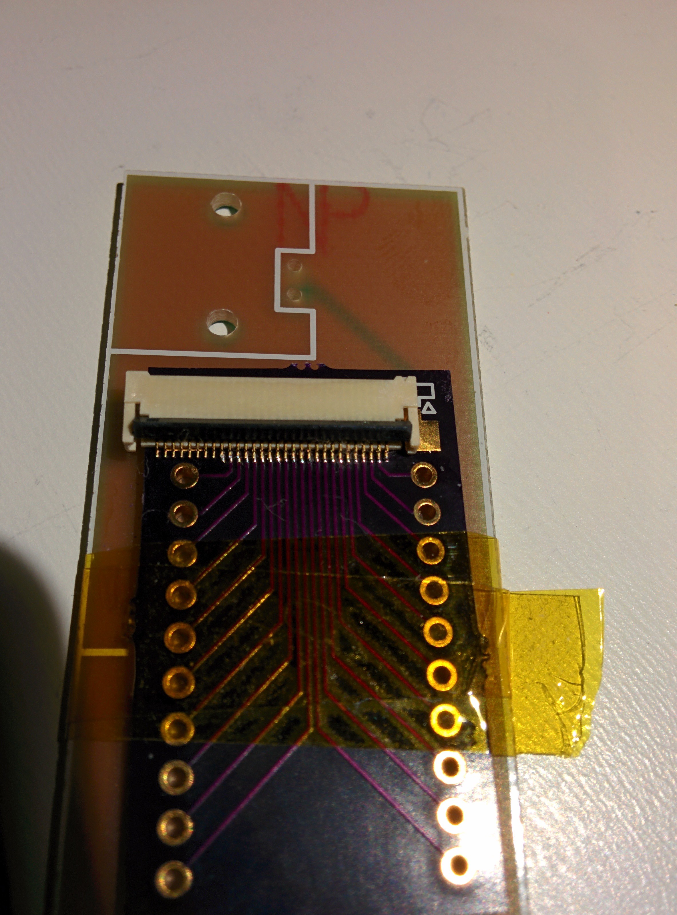
This way, pin 1 on my connector is aligned with pin 1 on the PCB footprint. When I plug my cable in, it will align correctly without effort.
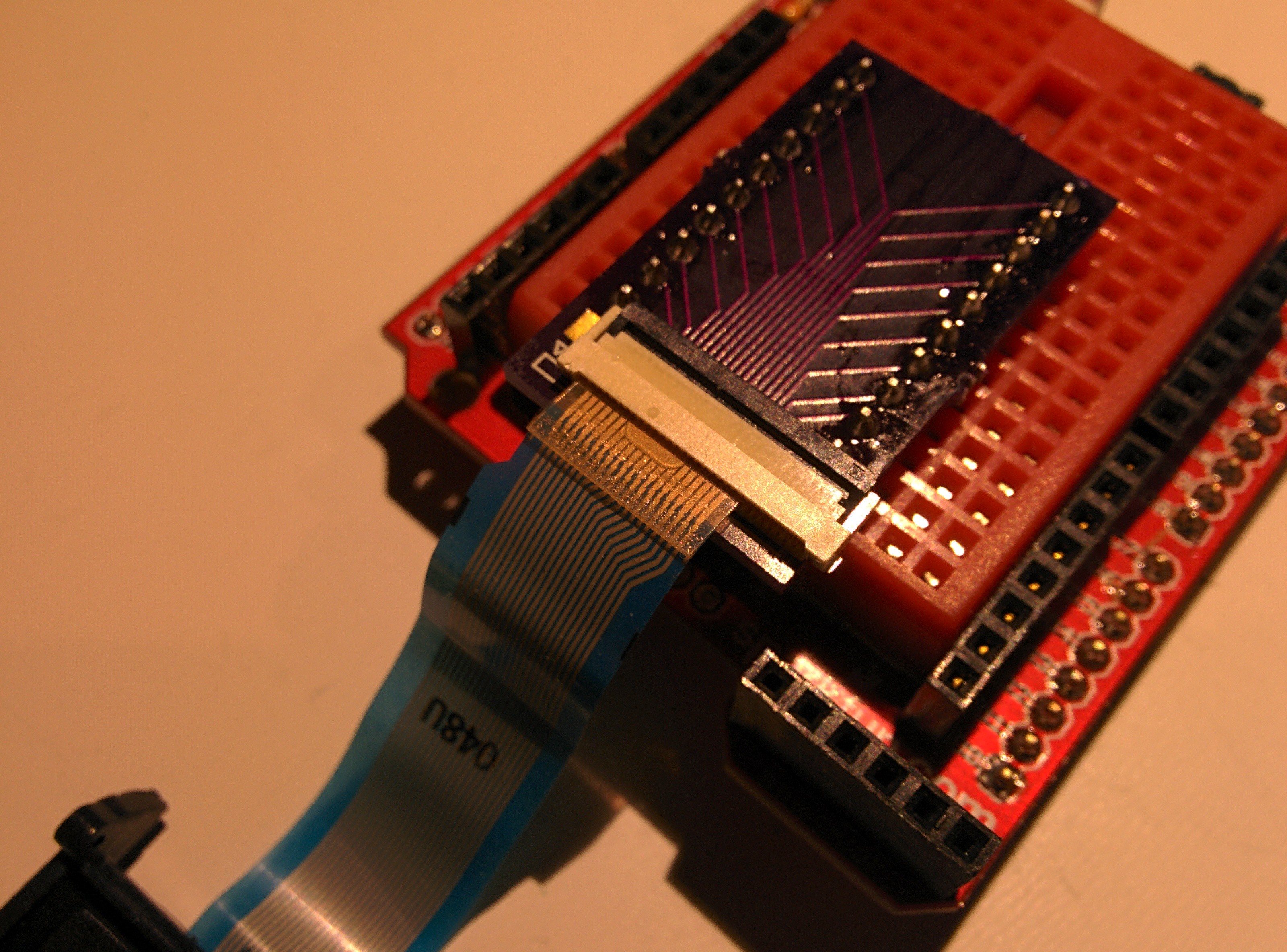
For this job, I also taped the breakout board down to a scrap PCB. This makes it a lot easier to manipulate the small PCB, and it is less likely to slide around when you are trying to get everything aligned.
This is what the finished job looks like after adding the pin headers. Note that even though the connector is offset, the cable is aligned correctly with the PCB.
Now it was time to move on with verifying that everything is working. I fired up my firmware, plugged everything in and... it kind of worked. Some keys worked perfectly, but some others were completely dead. I scratched my head quite a bit trying to figure out what the problem was.
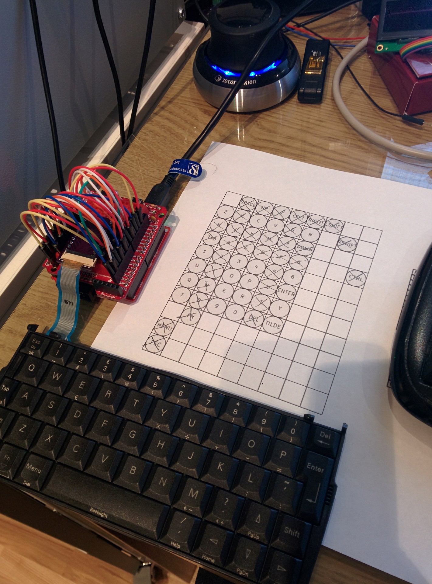
Paper and pencil are excellent debugging tools.
When facing madness, you respond with method. I worked my way through all keys, taking note of which ones worked and which ones didn't. It wasn't a pretty picture, only 18 out of 53 keys were working. I double-checked my wiring, but it seemed correct. Did I somehow break my keyboard when I opened it?
I took apart my "new" MC218 and carefully extracted the Scandinavian keyboard. When I plugged it in, I got the exact same result. So now I knew my problem wasn't in the keyboard.
Next, I suspected that I had made a mistake when tracing the electrical connections in the keyboard itself. I tried disconnecting the keyboard and measuring directly on the cable. This proved to be an exercise in futility, since it is nigh impossible to measure on two 0.25mm wide traces while pressing a specific key. I couldn't even measure anything on the keys I knew worked.
Instead, I thought about it for a while, and then decided to hack together a quick Arduino sketch with a different scanning routine. Instead of having a set of Rows and Columns to scan, it just scans all then pins connected to the keyboard, looking for contact between any two pins. For 20 pins, there are a few combinations to test. How many you ask?
There are 20 pins connected to the keyboard, but since we can't really connect a pin to itself, we have 19 connections for each pin. And since a connection between for example pins 1 and 5, is the same as a connection between 5 and 1, there is one pin less to test for each iteration:
That means that for any key I press, the Arduino has to test 190 different combinations of pins to be sure to find the pin combination for that key. Using my keyboard sketch as a starting point, I soon had a sketch that did this. Then it was just a matter of pushing each button in turn and noting which two pins became connected. I filled in a new spreadsheet while I did this.
There were still a lot of dead keys.
I had ruled out the keyboard, and now I also had ruled out my software, and the wiring logic. The only thing left was my connector board.
Breaking out my USB microscope, I found that the soldering job I felt so good about was horribly botched. Lots of pins were hovering above the pads, not making any connection. I tried fixing it to no avail. That's when you appriciate that OSHpark forces you to order three copies of every board. I found another connector and soldered it down on another board, making sure to make a better job this time. After that, everything worked perfectly!
In retrospect, I should have checked my soldering better. I can not see the problem without magnification even though I know what I am looking for, so double-checking tricky components with my microscope will be the new norm around my lab. I guess I'm getting old. :P
Also, it was actually a LOT quicker to scan my keyboard with the Arduino instead of my manual tracing. It was also more accurate (I found a few small mistakes in my original pinout). If I'm ever doing this with another keyboard, I'll go straight for the automatic approach.
Right now I'm cleaning up the keyboard firmware. I'll also start a project repo on GitHub, where all the schematics and stuff will be available. Then I'll get cracking on the keymap to get all the special characters right. Should be fun, but I'm doing it on my Raspberry just in case. :)
Discussions
Become a Hackaday.io Member
Create an account to leave a comment. Already have an account? Log In.
How is the hunt for the display getting on by the way?
Are you sure? yes | no
Well, I actually stumbled over a different supplier of the 5" HD OLED screen I was dreaming about. The price was $50 instead of $100, so now it's cheap enough that I dare to order it even though I don't have anything that can drive it yet. Even so, I can still get started with the capacitive touchscreen and write a linux driver for it. It will at the very least be a learning experience :)
I'm leaning more and more towards the Gumstix boards instead of the Raspberry compute module, and those have the correct interface to drive the display. There are also some gray-market adapter boards that could be useful, I'm still looking into them. I have at least got my hands on copies of the official interface specifications, that's a start :)
I'm getting my paycheck tomorrow, so I'm ordering the screen and some other stuff to play with, should be fun :)
Are you sure? yes | no
I know I'm getting old.. I used to be able to eyeball things like that 0.5mm connector, and solder them by eye too. No chance these days. Eveything gets the once over under the microscope. Well eveything under 0.1" that is... I'm not completely blind yet, through hole dip I can still manage fine.
Are you sure? yes | no
I know the feeling :) I struggled for way too long with switching out a few 0402 resistors on a device for work. I never been a soldering prodigy but small stuff is getting smaller... Now I always order solder paste stencils for my own designs and solder them with hot air. It saves a bunch of time for me!
Are you sure? yes | no