 michaelalink
The photobooth is together, well at least together enough that I am going to give it a trial run at a friends wedding this weekend.
The Outside:
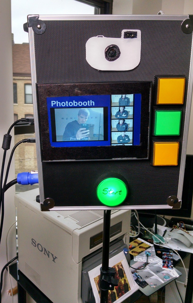
As of now only the start button is wired, and I changed it to a green button since that seemed more start-ey even though the big red button looked really fun. The three buttons on the right side are not wired but when they are they are supposed to be an up, down, and OK button so large groups can request additional prints after the photo shoot.
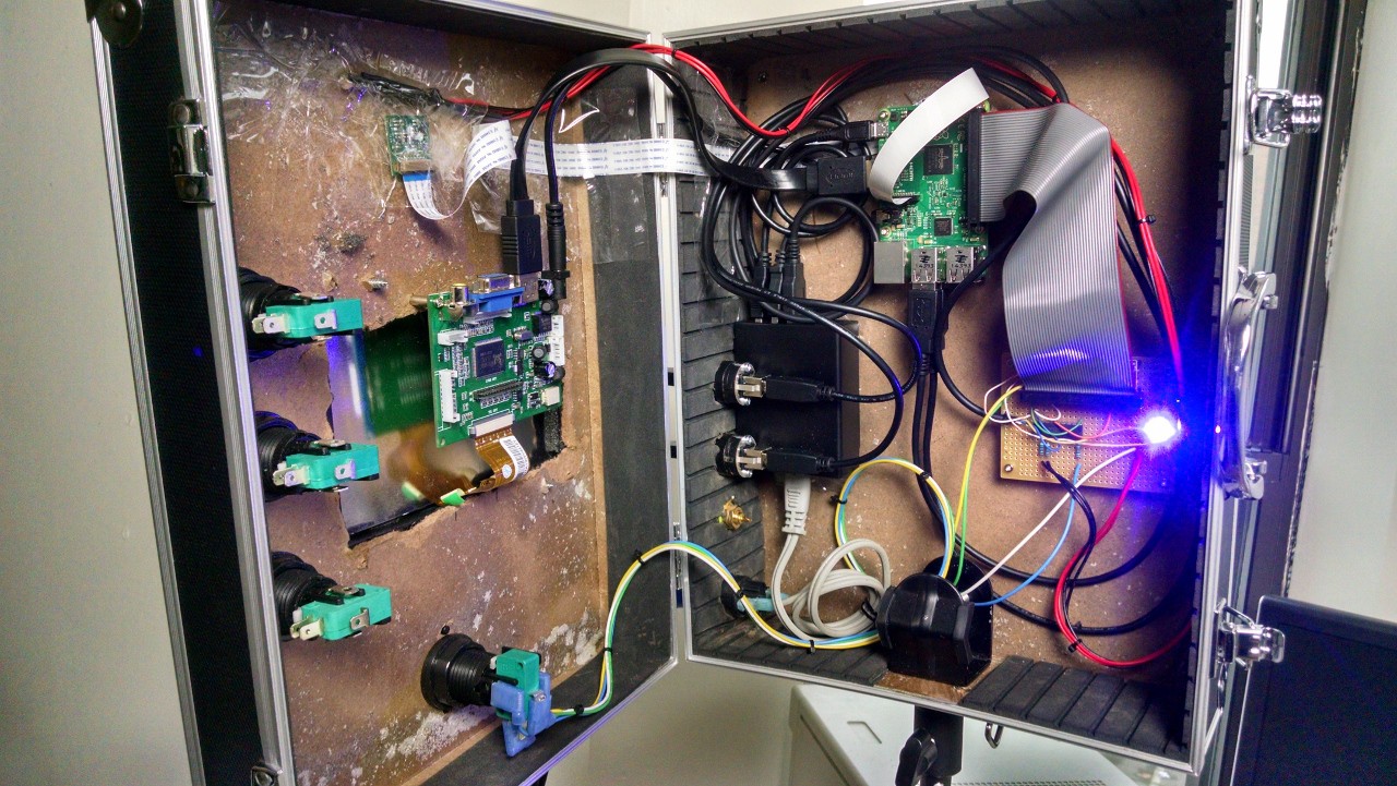
The Inside:
Raspberry Pi:
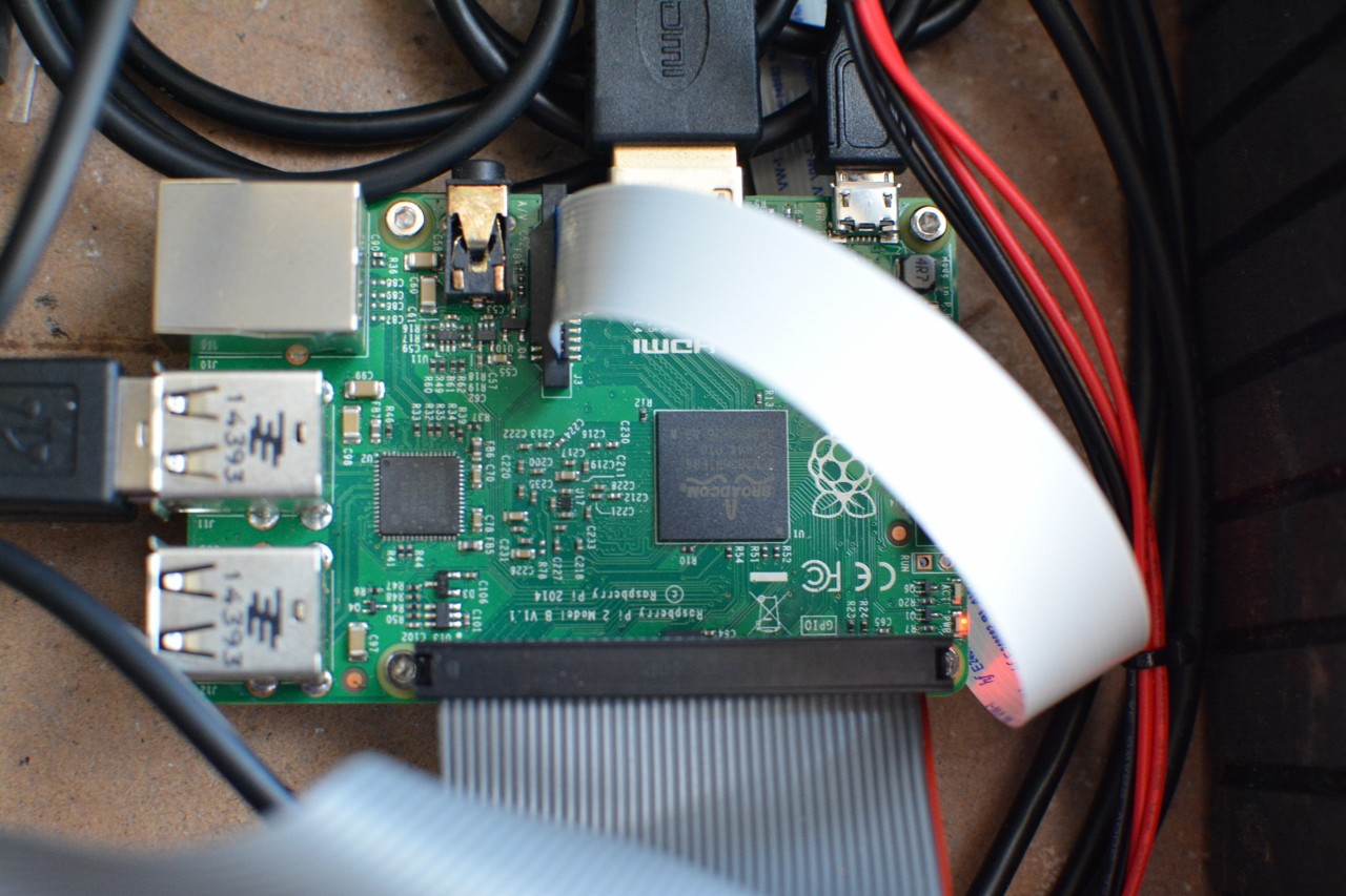
Well if you are on here you have probably seen one of these before so moving on.
Switch / LED interface board:
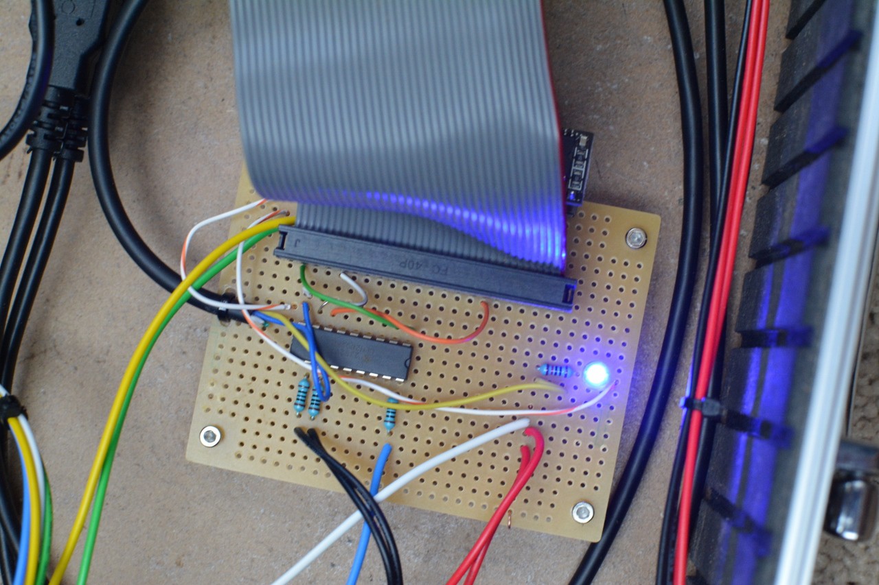
ULN2803 takes the 3.3V IO from the PI and switches the 5V from the power brick for the LEDs. Blue LED on the right is a status LED, whenever the board is connected it turns on. The switches are wired directly to ground and the GPIO of the PI. Hiding under the ribbon cable you can see the edge of the real time clock for the PI, still having a little trouble with the software for that guy.
Power / USB connectors:
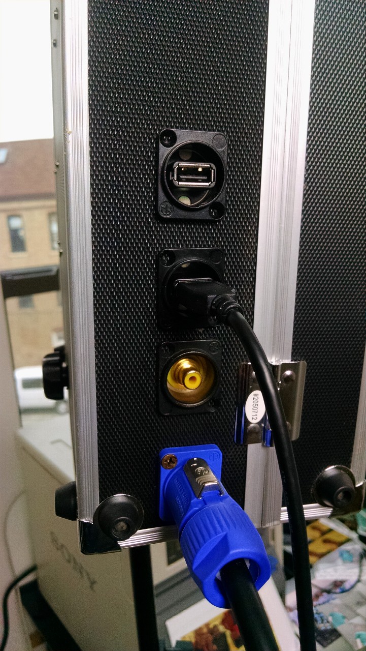
Power comes in through a locking Neutrik connector. Above that is a composite video out (not yet wired) the though being that could run to an external monitor and people can watch. Two USB ports above that, they just pass through to the PI; one for the printer, one for a keyboard to shutdown etc.
The Camera:
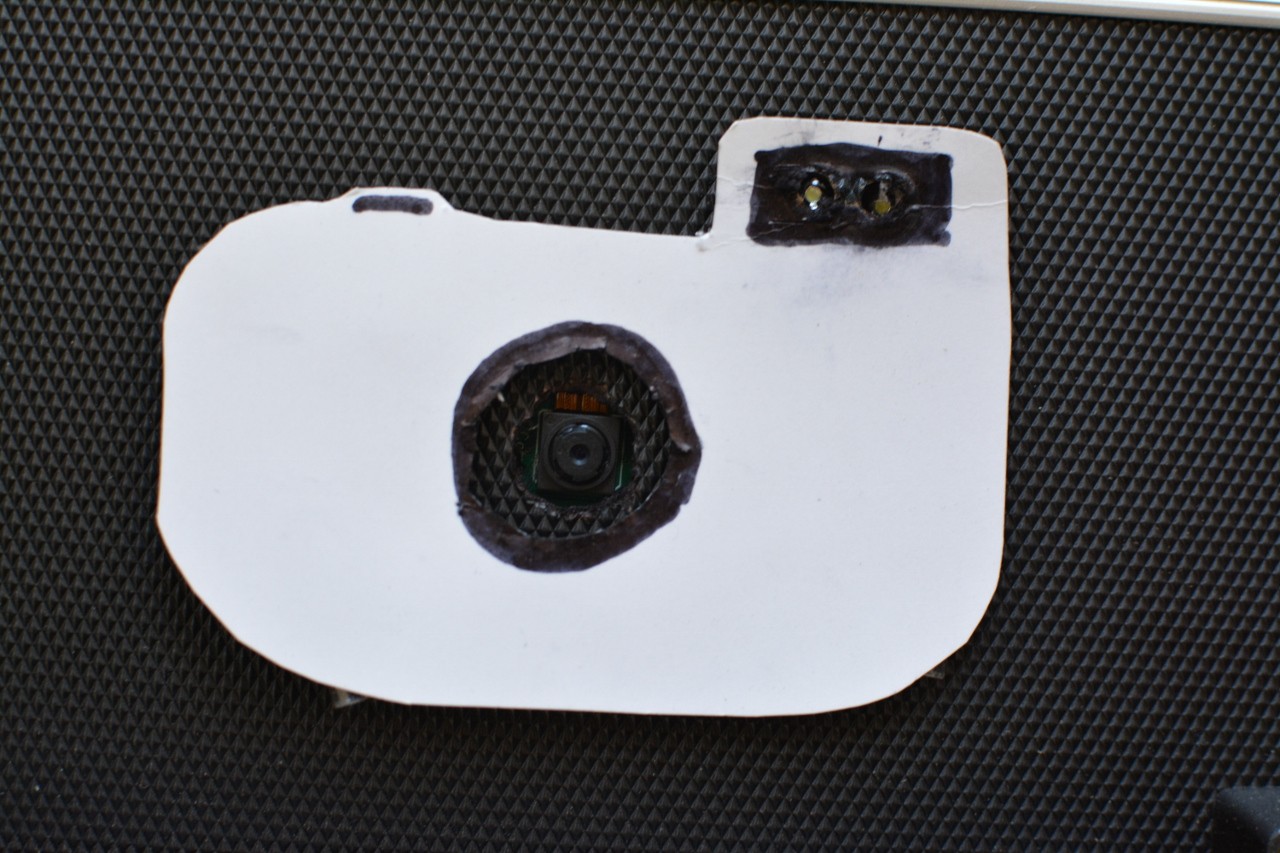
Pi Camera in the middle, and two white LEDs on the top right, turned on when the picture is taken. Looking at upgrading my beautiful camera cutout ...
LCD Driver Board:
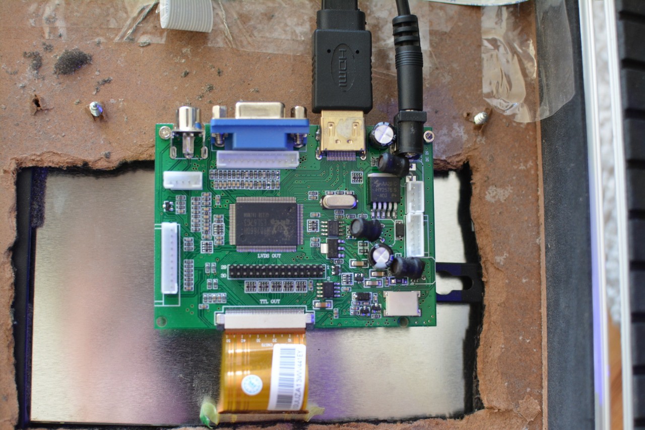
Not overly exciting, came with the LCD, hooked it up to 5V (instead of the called for 12) and it works fine.
Discussions
Become a Hackaday.io Member
Create an account to leave a comment. Already have an account? Log In.