 The Big One
Last night I finished the voltage calibration code for both setpoint and actual readings. It works by connecting a multimeter to get a known reading, and then setting the raw DAC output to find a known value + reading the ADC. You do this twice (for 0 and 8000 mV), and a bit of linear math gets you the slope and offset required. You can then save this to EEPROM.
From initial testing, this looks to be very promising. Across the entire range I was not getting an error rate of no more than about +/-10mV (i.e. +/- 1 on the least significant digit on my 2 decimal place multimeter). This may not be running into the 'precision' measurement range, but it is well within my desires for this supply. Also, this is done using a linear algorithm and two measurement points. By adjusting the measurement points (if you know you need 5v to be calibrated, use that as a point) or by using a non-linear calibration algorithm with multiple calibration points I could probably improve things (although I would really need a more accurate multimeter before I could do much more than what I have already).
Next up is the current calibration (both for current measurement as well as current limiting setpoints). I am planning on the same approach; most of the code is ready although it needs to be tested and fine tuned.
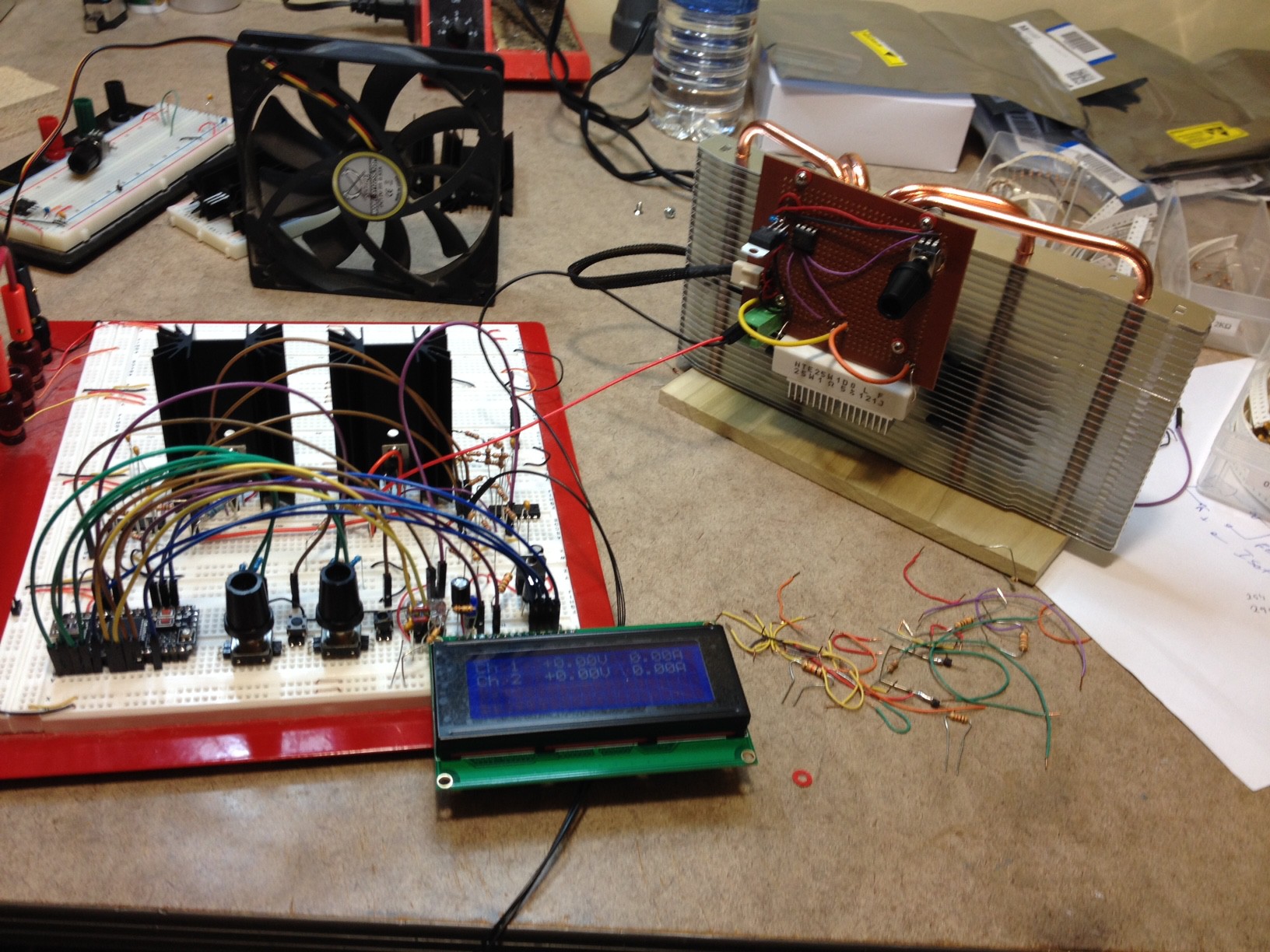
Finally, I thought I would share some pictures of my test setup.
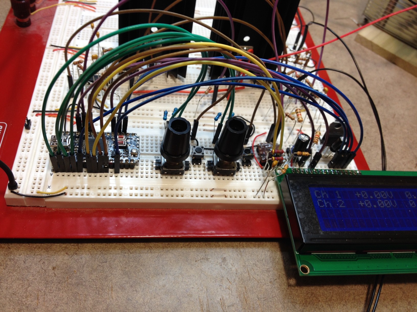
Here you can see the power supply (one channel, comprising two linear regulators + heat sinks with accompanying op amps, plus control board / encoders / display), with my constant current dummy load attached.
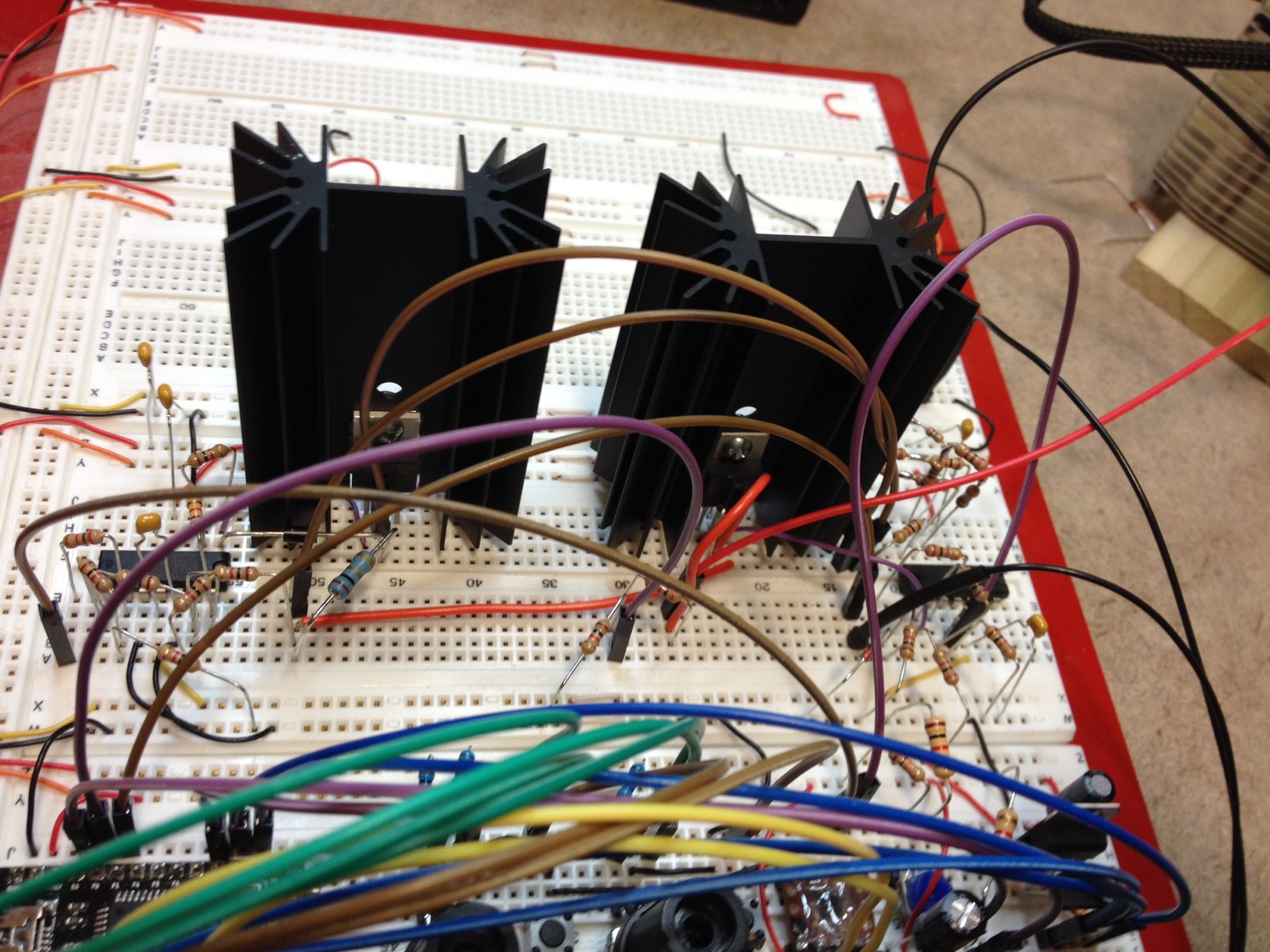
Here is a closeup of the two regulators and op amps comprising the single channel.
Discussions
Become a Hackaday.io Member
Create an account to leave a comment. Already have an account? Log In.
If you want the best accuracy you can use the Least Square Estimate with several points (10 seems to be good enough for such needs, the more the merrier).
I just did that for my project for the B3603 alternative firmware and it works very nicely. It also handles errors in the measurement range and works to minimize the errors. For laziness I simply used Python numpy but there is a simplification of LSE for the single variable case that can easily be done in a microcontroller if you have enough flash space.
Are you sure? yes | no
Awesome, thanks for the tip! I don't know if I will need it or not (more testing under various loads and voltages will help to show me if it is needed), but even just knowing what the name of the approach is will be a huge help. I would have had no idea what to even google for.
Cheers
Are you sure? yes | no
I also improve the ADC accuracy by oversampling, the theory is that I sample 64 times, sum them all and then divide by 8. This means I get 3 more bits of ADC accuracy and it works very nicely. In my case I improve a 10bit ADC to a 13bit ADC at the cost of 64 samples for each result.
Are you sure? yes | no
Yeah, I considered that... currently I am using a slow ADC clock (prescaler /128) and keeping a running average. So far my ADC readings are pretty much dead on to my multimeter readings... without a more accurate reference (my $30 multimeter goes to only 2 decimal places, and even it is not always consistent to 10mV) I don't think that I can improve the reading accuracy much.
Something that I *do* need to do is run the ADC readings in their own ISR. Currently I am polling from the main loop. While I have cycles to spare (in fact the majority of my main loop is spent in delay loops), it just feels wrong to do all that ADC work in the main program! ;-)
Are you sure? yes | no
So far I've been lazy as well and my ADC runs in main loop and not even using buffering features of the STM8S device. I'm not starved for cycles and the accuracy is good enough for me so I'm not bothering to change that either.
Also, one consideration that I have is that I sometimes prefer to avoid using ISRs unless they really contribute to what I need to achieve, otherwise they may steal cycles in the middle of some other operation instead of being in their own corner of work and get just as much time as they need without interrupting other work.
Are you sure? yes | no
BTW, your B3606 hacking looks really cool. Awesome work!
Are you sure? yes | no
Thanks! :-)
Frankly, I'm more impressed with a full-on design for a power supply than rewriting firmware for an existing device. But both methods achieve useful results :-)
Are you sure? yes | no
Yep, for sure... this is really my first foray into power electronics (like you, I am a software guy from way back who is slowly trying to teach himself electronics). There have been many false starts on this project, but I have learned a lot so it is all worth it IMHO. Plus, at the end I will (hopefully) have a device that solves a problem for me (and likely others). Win / Win! :-)
Are you sure? yes | no