 The Big One
Thanks to everyone for all the helpful comments! Based on feedback from here and elsewhere, we have decided to move away from the power op amps, and go with a more traditional power transformer design.
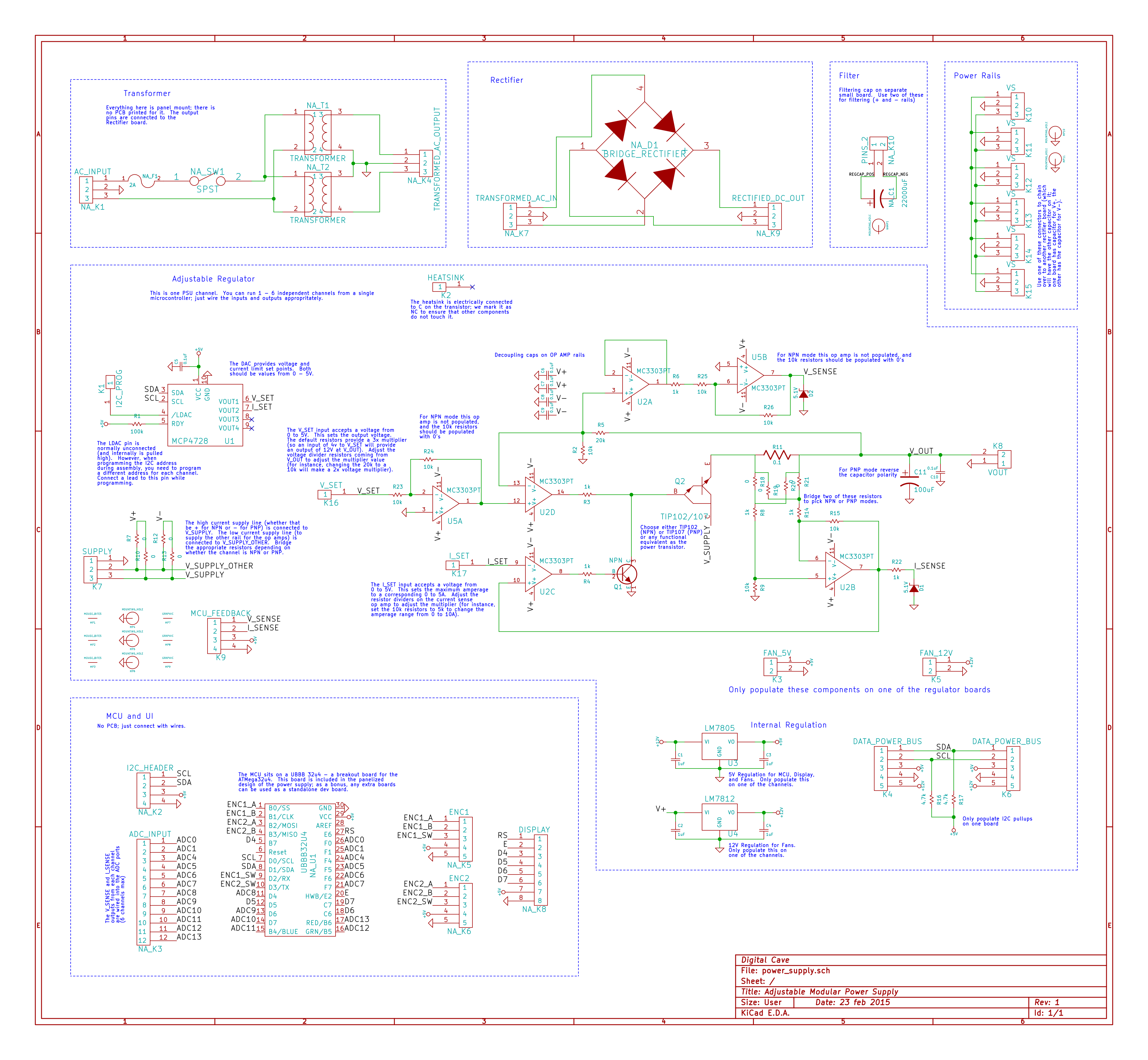
The design allows for a positive output from 0 - 12V (using an NPN transistor) or a negative output from -12 - 0V (using a PNP transistor). There are a few differences in the circuit; when soldering up a positive channel vs. a negative channel you will bridge different 0-ohm resistors to configure how things work. Furthermore, there is a need for an additional op-amp IC to invert the control signal and the voltage sense output on the PNP version.
Simulations of both NPN and PNP versions are available at https://github.com/thebiguno/microcontroller-projects/tree/master/projects/power_supply/simulation (run these simulations in the very nice circuit simulator available at http://www.falstad.com/circuit/directions.html ).
This design was mostly made by myself and [Exot], taking inspiration from a number of online sources including Dave Jones' power supply design video and [Bogdan's] WIP power supply. The really neat thing (for me at least) is that I actually understand how it all works, which is much better than just using an off-the-shelf component like I was planning on previously.
The cost per channel is now much lower as well (a very rough estimate is $15 / channel, although that can easily be reduced if you scrounge some spare parts). The main microcontroller board, display, and encoders will run you about $20 if you source certain parts more intelligently (i.e. get the HD44780 display from eBay, not Digikey). The main power supplies can also vary in cost quite a bit... if you go with dual high amperage switch mode supplies (for positive and negative rails) it will run you about $60, but if you are only interested in positive (and if you don't care about having the voltage go all the way to 0), you should be able to run this off a wall wart.
I have decided that (eventually, at least) I will make 6 channels (4x positive, and 2x negative). I am going to power them with two switch mode power supplies connected together in series, with the connected rail tied to ground, giving me a +/- 15V supply (buying two switch mode supplies is still quite a bit cheaper than buying a high amperage transformer + the associated support components). [Exot] will have a smaller channel count, and will probably power his with a more traditional transformer + rectifier circuit, as he already has those on hand.
The board can be controlled via a microcontroller + I2C DAC (one DAC chip per channel), or can be controlled with a couple potentiometers. Basically the only requirement is that a varying voltage from 0-5V is applied to both the V_SET and I_SET inputs. Given the resistor values on the board, this will result in an output voltage of 3x the set point voltage (i.e. to get 12V out, apply a voltage of 4V to V_SET) and 1x the set point current (i.e. to get 3A max current out, apply a voltage of 3V to I_SET). You can easily adjust the value of the resistors to change these multipliers if you want more or less voltage / current output.
I plan on ordering the parts this coming week and putting them together on a breadboard, so that I can verify the operation in real life. I have already breadboarded this circuit using low power transistors, which is all I have available in my parts bin, and it works beautifully.
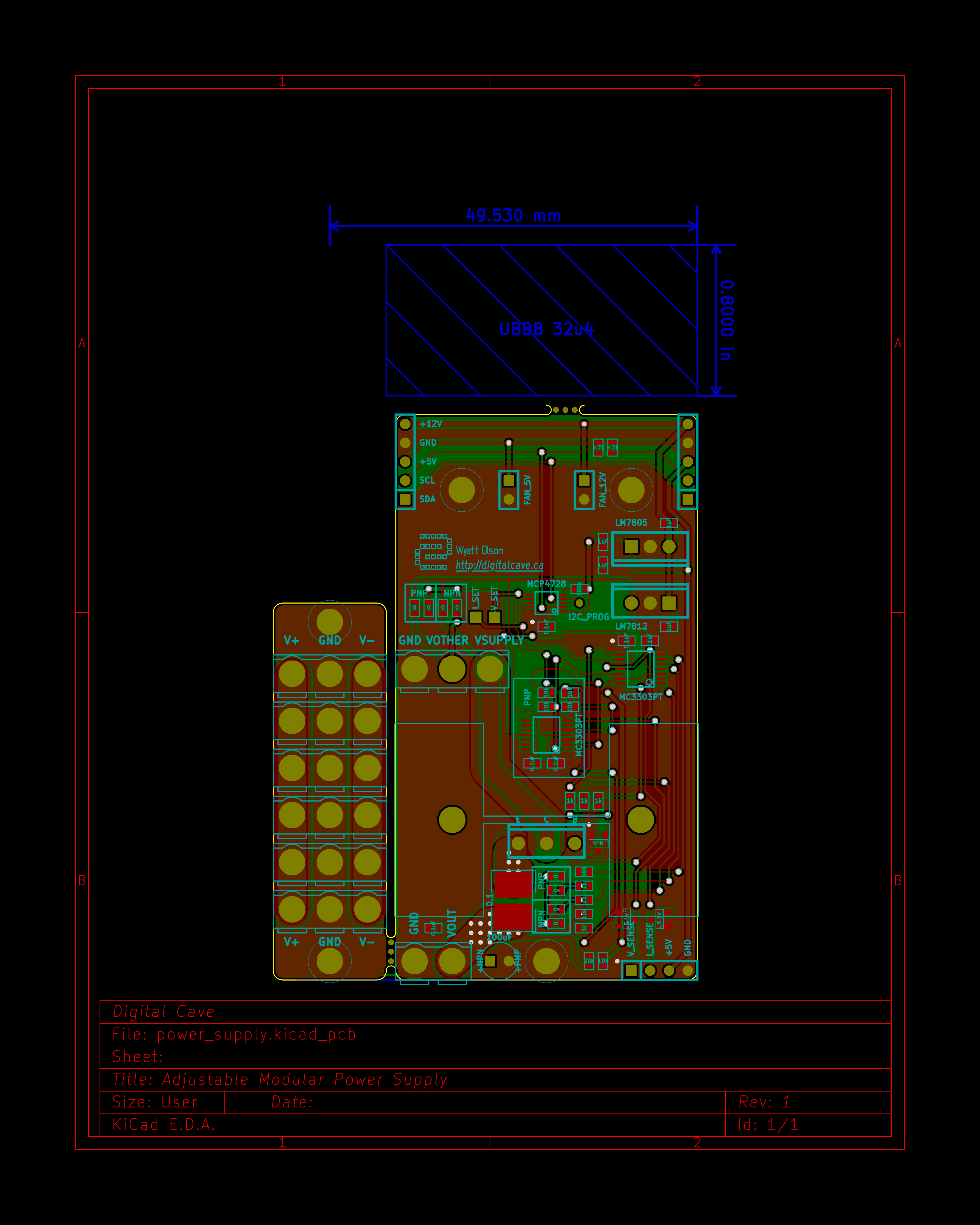
The boards are routed and ready to be ordered once the breadboard circuit is verified. The current version is below (the microcontroller will be in the blue shaded area, and I am not sure whether or not I will include a rectifier board):
I think that just about covers it... even with all this work, I have yet actually make anything physical yet (well, other than the software demo and a low power breadboard version). Hopefully that will have changed by next weekend.
Cheers
Discussions
Become a Hackaday.io Member
Create an account to leave a comment. Already have an account? Log In.