Close
0%
0%

UpLift Desk wifi link

Add a WIFI link to an UpLift Desk and control it remotley

Similar projects worth following
We recently upgraded our office furniture and we each got a new UpLift standing desk. these desks have variable and programmable height with a small (wired) remote installed on the front of the desk.

Main purpose of this project is to install a hidden controller on my co-workers desks so i could mess around with them and change their desks height remotely.

As a bonus, i would also like to add a "WTF??" mode to the desk that`ll block the wired remote, start randomly changing the height of the desk and flash the number 666 on the display while the setting is changing.

Lastly - these desks are ridiculously expensive so whatever hack I do, I cannot break/open/soldier/cut or do anything too intrusive or irreversible to them

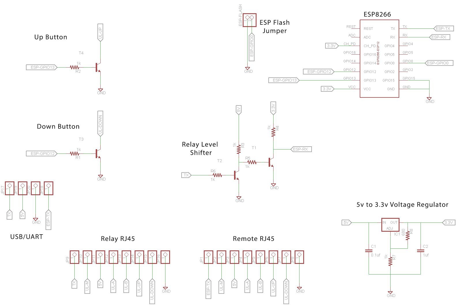
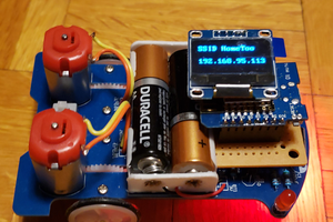
I`m going to try and make the end results as cheap as possible so i could build controllers for our entire office (8 desks right now) for that reason I have decided to use a standalone ESP8266 as both the WIFI transceiver and as a controller with minimum hardware

  • 1 × ESP8266 WIFI and controller

  • Git Repo

    Yadid Ramot02/04/2015 at 19:57 3 comments

    Git repo is now up on - https://github.com/eyadid/uplift-wifi

  • Schematics + Web Interface

    Yadid Ramot02/04/2015 at 19:41 0 comments

    Iv'e created 3 REST endpoints for the desk and uploaded them to the ESP :

    http://[DESK IP]/up - increase height - will signal the UP button for 200ms (click simulation)

    http://[DESK IP]/dn - decrease height - will signal the DOWN button for 200ms (click simulation)

    http://[DESK IP]/st - state read - will read the serial input from the relay unit and display the results

    To save space and ease development, iv'e decided to host the web interface on S3 and call the API by embedding a <script> tag on the page. The script will call the ESP which in turn returns a JS command - "results(key,val);".

    An example of the interface is up here :

    http://deskcontrol.s3.amazonaws.com/index.html#[IP OF DESK]

    Currently working on setting up a git repo for this project. will update as soon as it`s up

    as for the schematics - the components I needed were : 3.3v regulator, 5v to 3.3v level shifter, the ESP and a TTL header (for programming / updates)

    I finished drawing the initial design and looks like it`s working. (attached)

    next step - PCB fab + 3D print enclosure and we're good to go

  • Data analysis

    Yadid Ramot02/03/2015 at 02:30 0 comments

    Looks like the relay unit sets the brown wire (#2) to high for ~20ms then send a reset sequence and the height value in inches

    0 1 0 0 0 0 0 0 0 1 0 1 0 0 0 0 0 0 0 1 0 1 0 0 [BITS FOR HEIGHT]

    Each bit is ~100us long (9,600 bps? My "logic analyzer" is a nice debug toy but can't get accurate readings out of it)

    EDIT : ** Just confirmed that the relay unit is sending 16bit integers over 9600bps.

    the format is [257][HEIGHT][257][HEIGHT]....

    here are some samples -

    32.9 = 1 0 1 0 0 1 0 0 1 0 (329 = 01 0100 1001)

    32.8 = 1 0 0 0 0 1 0 0 1 0 (328 = 01 0100 1000)

    32.5 = 1 0 0 1 1 0 0 0 1 0 (326 = 01 0100 0110)

    32.4 = 1 0 0 0 1 0 0 0 1 0 (324 = 01 0100 0100)

    32.1 = 1 0 1 0 0 0 0 0 1 0 (321 = 01 0100 0001)

    31.8 = 1 0 0 1 1 1 1 1 0 0 (318 = 01 0011 1110)

    29.8 = 1 0 0 1 0 1 0 1 0 0 (298 = 01 0010 1010)

  • Remote Connector

    Yadid Ramot02/02/2015 at 20:38 0 comments

    Found some background info about the controller and relay box. they are both off-the-shelf components manufactured by JIECAN

    Controller spec - http://www.jiecang.com/upload/file/enPDF/JCHT35K.pdf

    and Relay spec - http://www.jiecang.com/upload/file/enPDF/JCB35N.pdf

    I couldn't resist opening the remote. This is what i know about the pinout -

    1. Transparent - "M" button (when set to LOW)
    2. Brown - Digital - guessing it`s for data display (5v TTL)
    3. Black - GND
    4. White - ?
    5. Red - +5v
    6. Purple - ?
    7. Green - UP button (when set to LOW)
    8. Yellow - DOWN button (when set to LOW)

    Next, doing some bit sniffing for the display.

  • First examination

    Yadid Ramot02/01/2015 at 00:14 0 comments

    The desk have 2 main electronic components - a relay box that controls the motors and a small wired remote that controls the relays and display current setting.

    The remote have 7 buttons - UP, DOWN, 4 programmable heights and 1 button to program the 4 stored heights. the remote also have a small 3x7-segment/LED display that shows current height.

    There is a standard RJ-45 connection between the remote and the relay box

    There is an additional socket right next to the RJ45 connector that's just a little bit bigger than a standard phone jack (connector is currently not in use)

    More about the desks - http://www.upliftdesk.com/

View all 5 project logs

Enjoy this project?

Share

Discussions

salsabeard wrote 01/10/2020 at 16:00 point

I recently implemented a sit/stand desk in my house and I've been looking into doing something that you seem to have already done.  The desk I picked up is a quad-leg design using dual motor controls and a memory control set as well.  It took me forever to figure out what controllers it was using, but once I did I found your project immediately. 

My intention was a bit more extensive than just a wireless switch.  I would like to create a Home Assistant component that can push state changes, automate up/down to specific heights, and also display current height.  Lastly, like you, I want to do this as a stock implementation without modifying the current hardware.  If my understanding of your project is correct, you made your unit design to be inline with the control switch.  Since my desk makes use of a linked dual controller design, I was thinking to connect the wireless module to the control port on the secondary motor controller, but an inline solution would work just as well.

Anyway, did you have success getting this project to work?  Do you mind if I offer up my setup as a testbed?

  Are you sure? yes | no

alister wrote 06/23/2016 at 22:06 point

Do you have any photos of the final product? 

  Are you sure? yes | no

alister wrote 06/26/2016 at 17:23 point

will contribute beer money if you can find a few minutes to upload  few more pics of the project

  Are you sure? yes | no

Lane wrote 06/10/2016 at 23:49 point

Hi Yadid, did you ever get this working?  Looking at the schematics I can't figure out how it'd work with JP8 not connected to anything.  According to the diagram, that should be ground from the remote, so it seems like something should be attached there.  Also, the 0.1 uf capacitor labelled C1 only has one of its legs attached to anything.

Nice work!

  Are you sure? yes | no

alister wrote 06/02/2016 at 22:05 point

would you consider adding instructions or posting photos of the final product? Close to done but could use a bit of help. 

  Are you sure? yes | no

Infamy wrote 02/18/2016 at 07:48 point

Did you ever the PCB for this in the end?

  Are you sure? yes | no

varad thakur wrote 02/10/2016 at 19:44 point

great project, thanks.

In my case the up arrow is not working on that remote itself, where as the downarrow is working. Any suggestion? Also how can i get the IP of the remotebox

  Are you sure? yes | no

Yadid Ramot wrote 02/10/2016 at 23:41 point

try shortening the green wire to GND (pin #7) and see if it works. if not, then it`s probably a problem with your relay (and not the remote) - not sure how i can help you there. 

to get the IP you can just go to your DHCP server and look for the MAC of the ESP.

  Are you sure? yes | no

Similar Projects

Does this project spark your interest?

Become a member to follow this project and never miss any updates