 Gertlex
There are several directions I could go with this, and definitely limitations to be had.
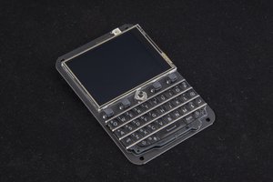
I think my biggest goal is to figure out the interface to manipulate the e-ink keys. After some basic searching I did not find any hacks or similar keyboards.
The idea of having a functioning Linux terminal with display + keyboard would be the ultimate version of this... I probably won't get that far. I suspect I won't be using the phone's display, but I don't know anything about the displays used in phones of 5 years ago, either. The Edison doesn't have VGA/HDMI/etc display output, but there are some projects that use the simple TFT screens that are commonly paired with Arduinos. I'd use one of those, I figure.
To help myself make continual project, small goals are a good idea. Some of these:
- Buy an Edison and play with it!
- Create a breakout board for the keyboard, just to see if I can identify what happens when the keys are pressed. Also see if I can identify how the keyboard is powered (voltage, pins).
- Create a breakout for keyboard and/or display that lets me monitor communication with the mainboard using either an oscilloscope or a logic analyzer.


 arturo182
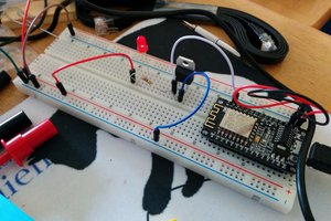
 WJCarpenter
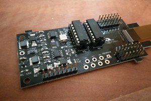
 sapir
sapir
 Dávid Máté
I was digging a bit on this tonight and found a couple things. The display (and maybe the buttons?) is handled by the Dialog DA8531 chip in the phone. I found some documentation saying it's controlled by SPI. There happens to be four pins just beside this chip. My hope is it's the SPI connection to this chip can be intercepted here.