 Jared Sanson
The next big problem I have with the Portege LCD is that the connector is tiny and it's not possible to solder wires to it. So I started making a breakout board for it:
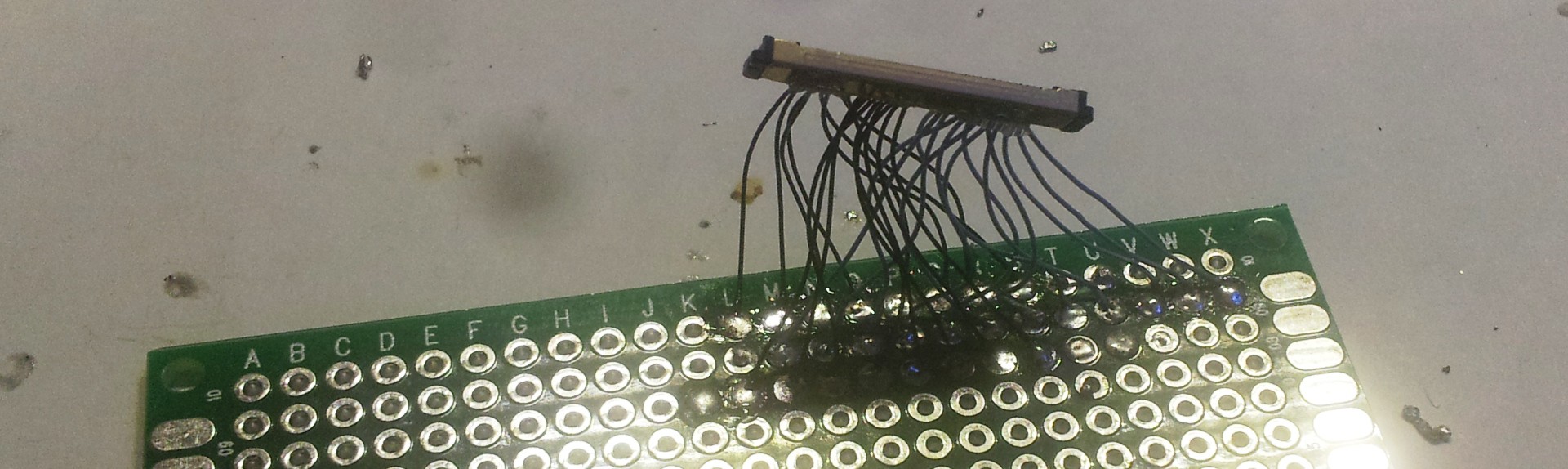
It was very very tedious work, and in the end it didn't even work :( Somehow the wires inside the connector shorted through to the case.
So I decided I should do it properly and make a breakout board, complete with backlight driver. To reduce the risk of things going wrong I decided to use the same backlight driver chip as the laptop (MAX8790 6 channel LED driver)
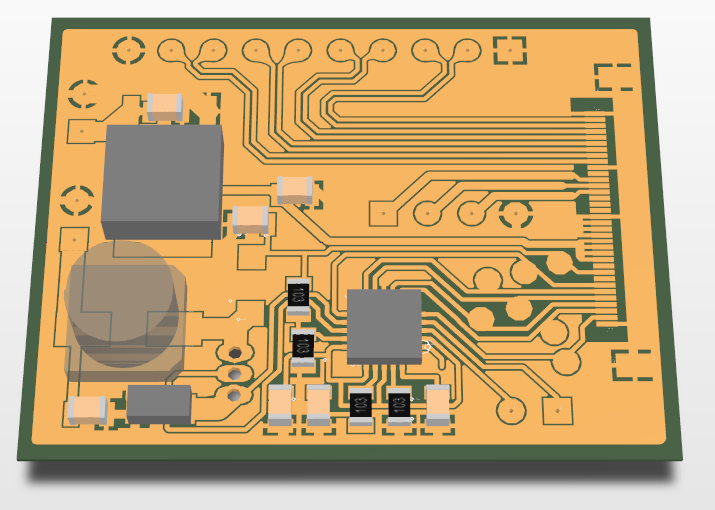
Because I was feeling impatient I decided I would try to etch it at home instead of ordering online, so I designed the PCB to be single-layer with only SMD components. The LVDS signals are routed through to larger pads to make it possible to solder, and there's also some breakout pads for the EDID I2C lines as well.
I wasn't actually sure if it was possible to etch a PCB with traces that fine (the SMD connector pitch is 0.4mm, and the LVDS traces are 0.254mm wide!!), but I wanted to give it a shot anyway!
It took me 4 attempts to actually get the iron-on toner transfer to stick properly, since the first few times I overheated it and melted the plastic sheeting, but in the end it paid off!
I then etched it in an ammonium persulfate solution:
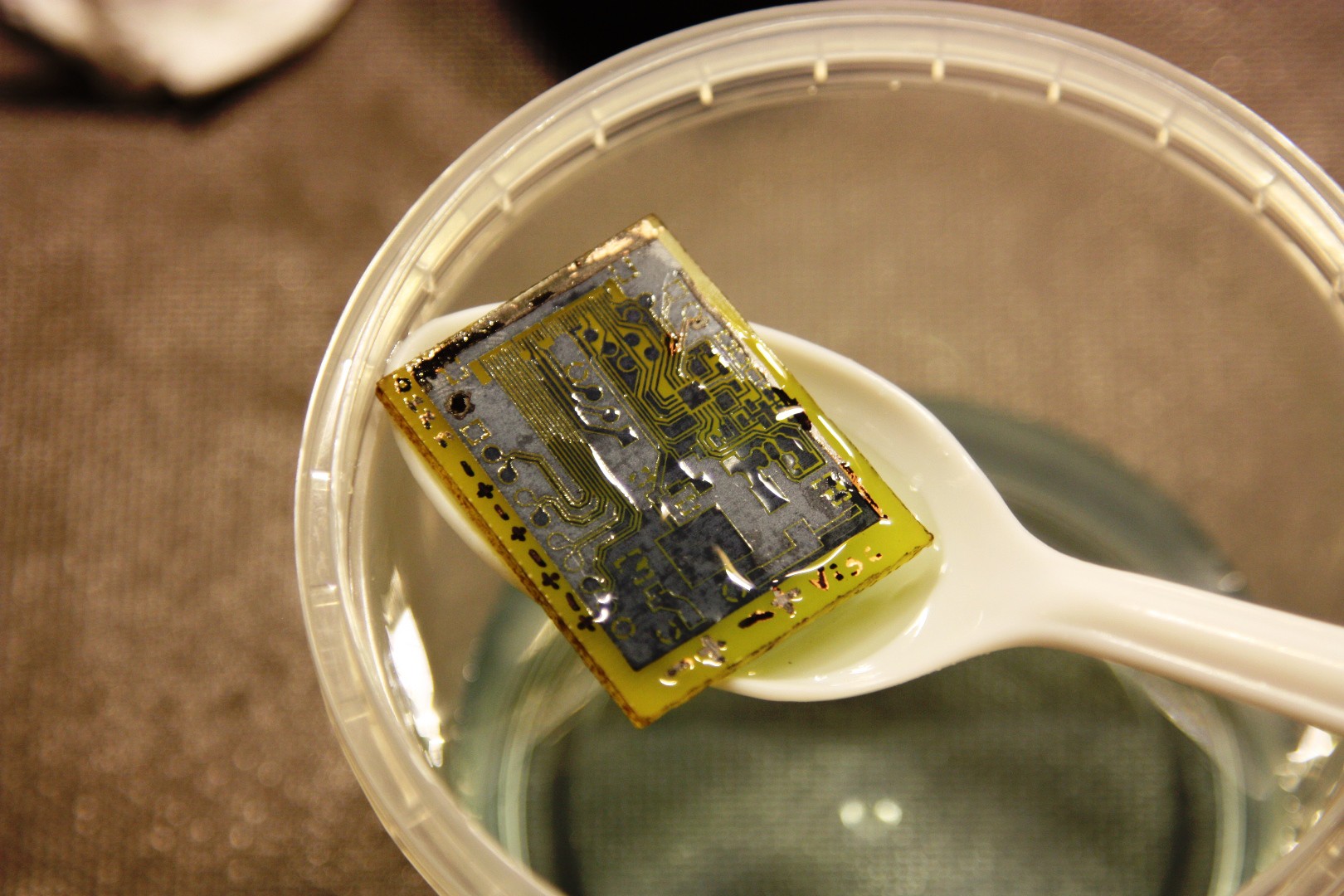
Although it looks perfect, the etchant had gone way too far and had eaten all the LVDS traces, which you can see in the next photo (the PCB on the right):
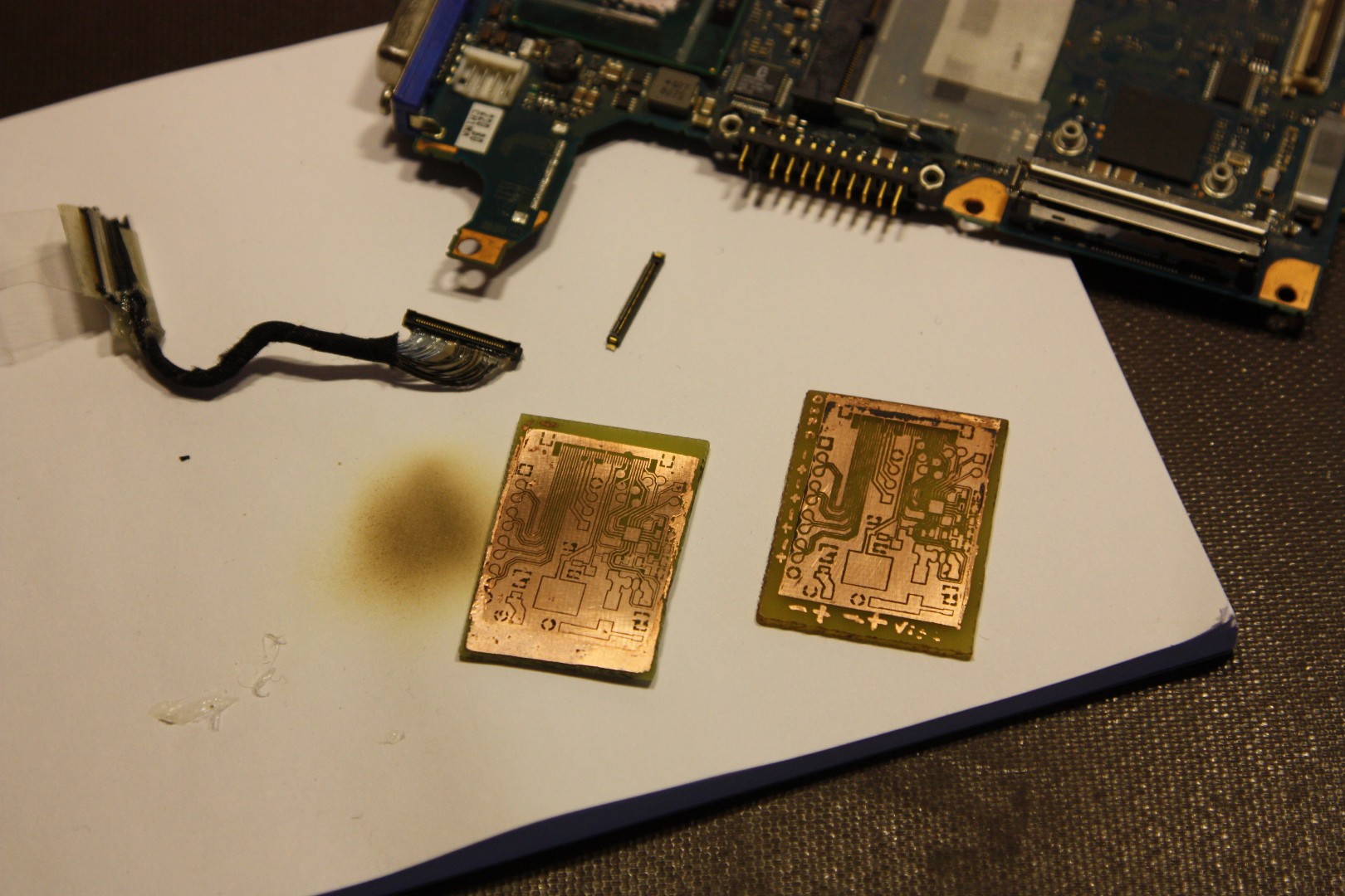
Fortunately my second attempt was almost perfect! (Apart from some microscopic shorts which I managed to remove with a little bit more etching)
An interesting note I found about using ammonium persulfate: You must have the solution (water and ammonium persulfate crystals) in the right proportions! Too weak or too saturated and it won't etch properly! This caught me off guard because I naively thought a stronger solution would just etch it faster, but there must be some chemistry happening when the solution becomes completely saturated preventing it from doing anything at all.
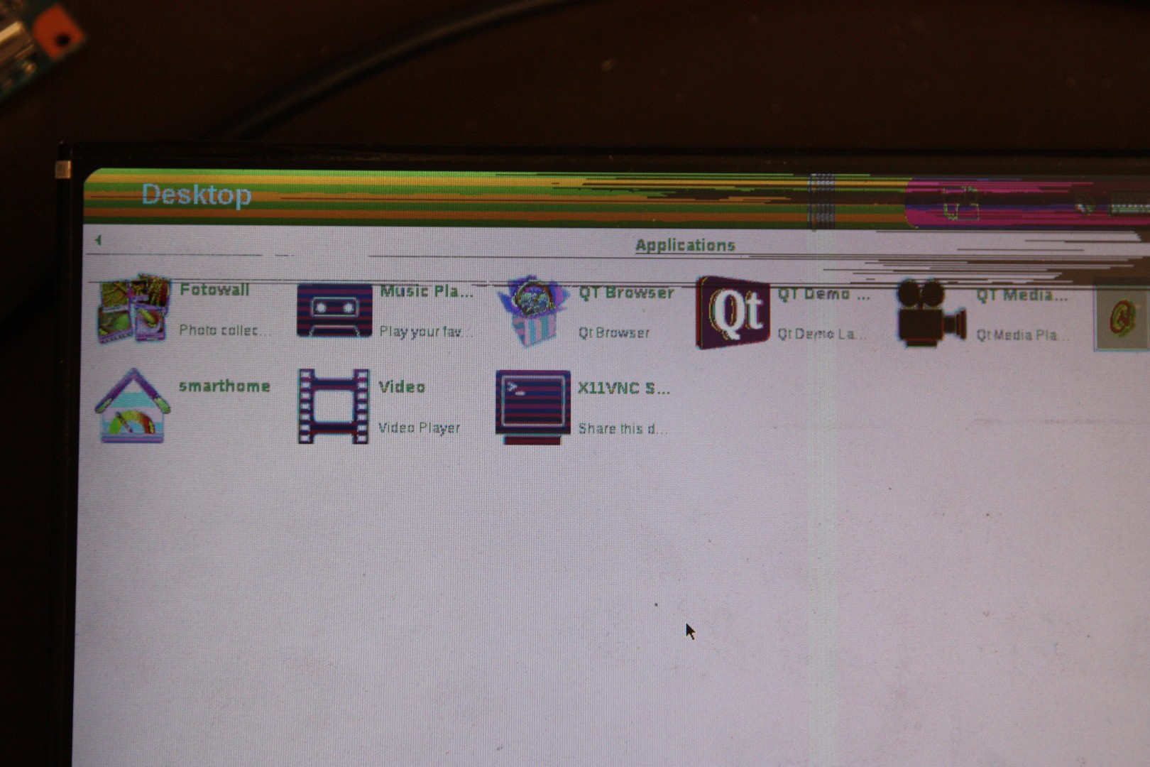
After some quick soldering I powered it up and connected it to my RIoTBoard, and much to my surprise it powered up and worked first try! The only flaw being I had two of the LVDS data pairs swapped, so the colours came out a bit funny.
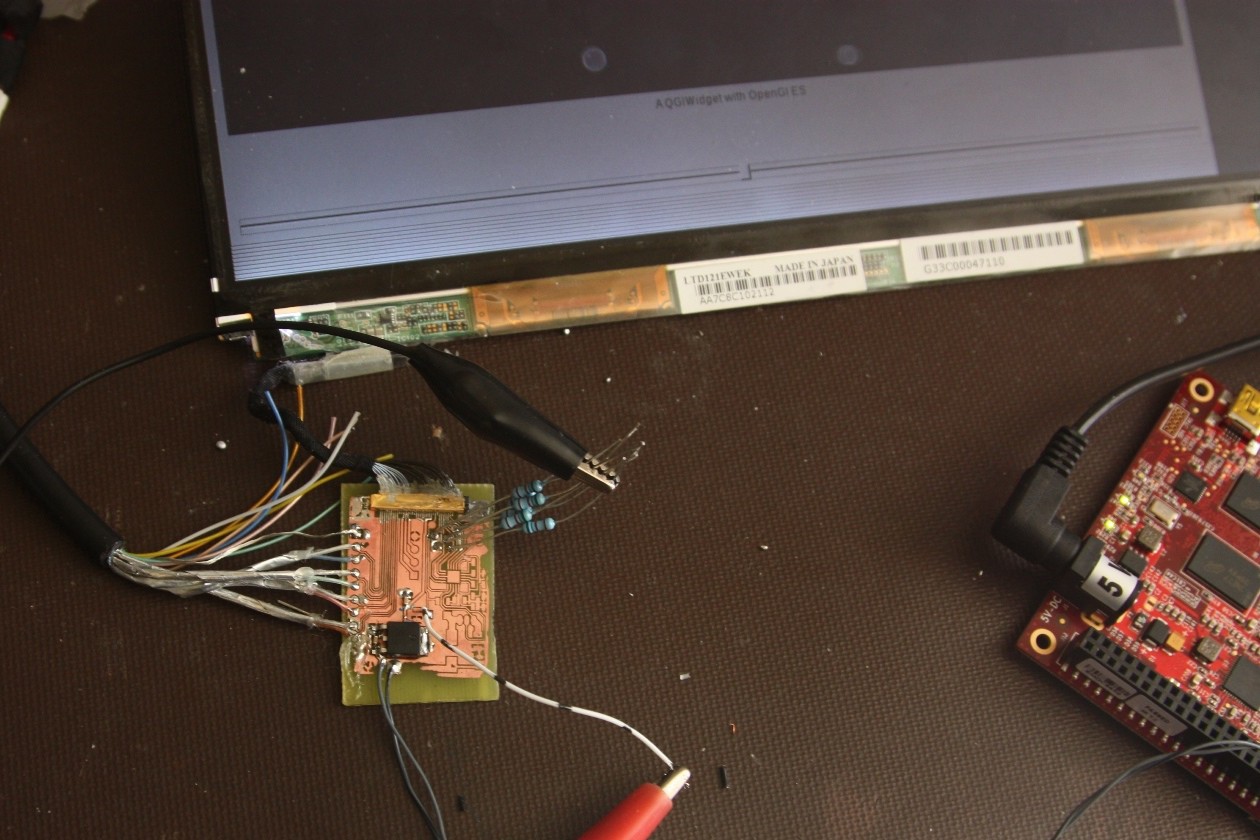
Project success!
Now I definitely have plans for this LCD, since it is sunlight viewable! The contrast isn't quite as good as e-ink or the Pixel-Qi display, but it retains colour even in full sunlight, and is definitely usable unless the sun is directly reflecting on the display.
Still to come:
- The backlight driver
- Getting the RIoT board to output the right resolution (note in the first image that there's some empty black area to the right)
Discussions
Become a Hackaday.io Member
Create an account to leave a comment. Already have an account? Log In.
I have two laptops from which I extracted the hard drive, the dvd-r and the memory, only is left the screen, I found in amazon two of this kind of boards, but not having any reviews I don't trust so much on them...
I want to ask, how much power it consume?
how many volts are required, and how you knew which one are the cables for energy... What is the risk doing this way?
I want to try also, but I'm not so sure about the risks...
Are you sure? yes | no
You should try to find a datasheet if you can - try searching google for any part numbers you see on the LCD, and add 'filetype:pdf' to narrow down the results.
Can you still run the laptops and display something on the LCD? It's much easier to figure out the pinout if you have a live system!
The voltage to drive the display will probably be either 2.4, 3.3, or 5.0V, but there's also the backlight to watch out for.
You may find my article here useful: http://jared.geek.nz/2015/apr/driving-fpdlink-displays#reverse-engineering
Are you sure? yes | no