 James Newton
Not sure why I never linked to this video... it does a pretty good job of explaining the basic idea.
0%
0%
Reagent Robot
Automate the Reagent (take a sample, put a drop of stuff in, shake, look at the color) testing of water for Aquaponics, Ponds, Aquariums.
Become a Hackaday.io member
Already have an account? Log in.
Just one more thing
To make the experience fit your profile, pick a username and tell us what interests you.
Pick an awesome username
hackaday.io/
Your profile's URL: hackaday.io/username. Max 25 alphanumeric characters.
Pick a few interests
Projects that share your interests
People that share your interests
 you can see the TIP122 driver for the valve hanging upside down on the back of the BOB. Colored wires are stepper motor leads. Ribbon cable is the PMinMO standard connector from the BOB to the


 Quinn
Quinn
 zakqwy
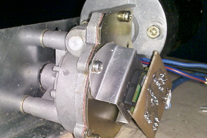
 Alastair Young
Between my day job and consulting, I'm totally jammed for time. Is anyone out there interested in helping with the colorimeter part? Here is what needs to be done: Wire up the light to frequency converter and a neopixel to an Arduino, then code it up and do some tests to verify that it seems to accurately measure colors. I'm willing to reimburse parts cost, and trade stuff for the work... Help?