 Jeremy
The last couple months have been BUSY. Here's an update on all of the things we've been working on.---------- more ---------
Floor Square Size and Plastic
Originally we wanted the floor squares to be 14" x 14". Nick, who is a structural engineer by day, did some stress testing and found that using half-inch acrylic wouldn't be strong enough to reliably withstand the load of "the drunk hippie stomping" on it.
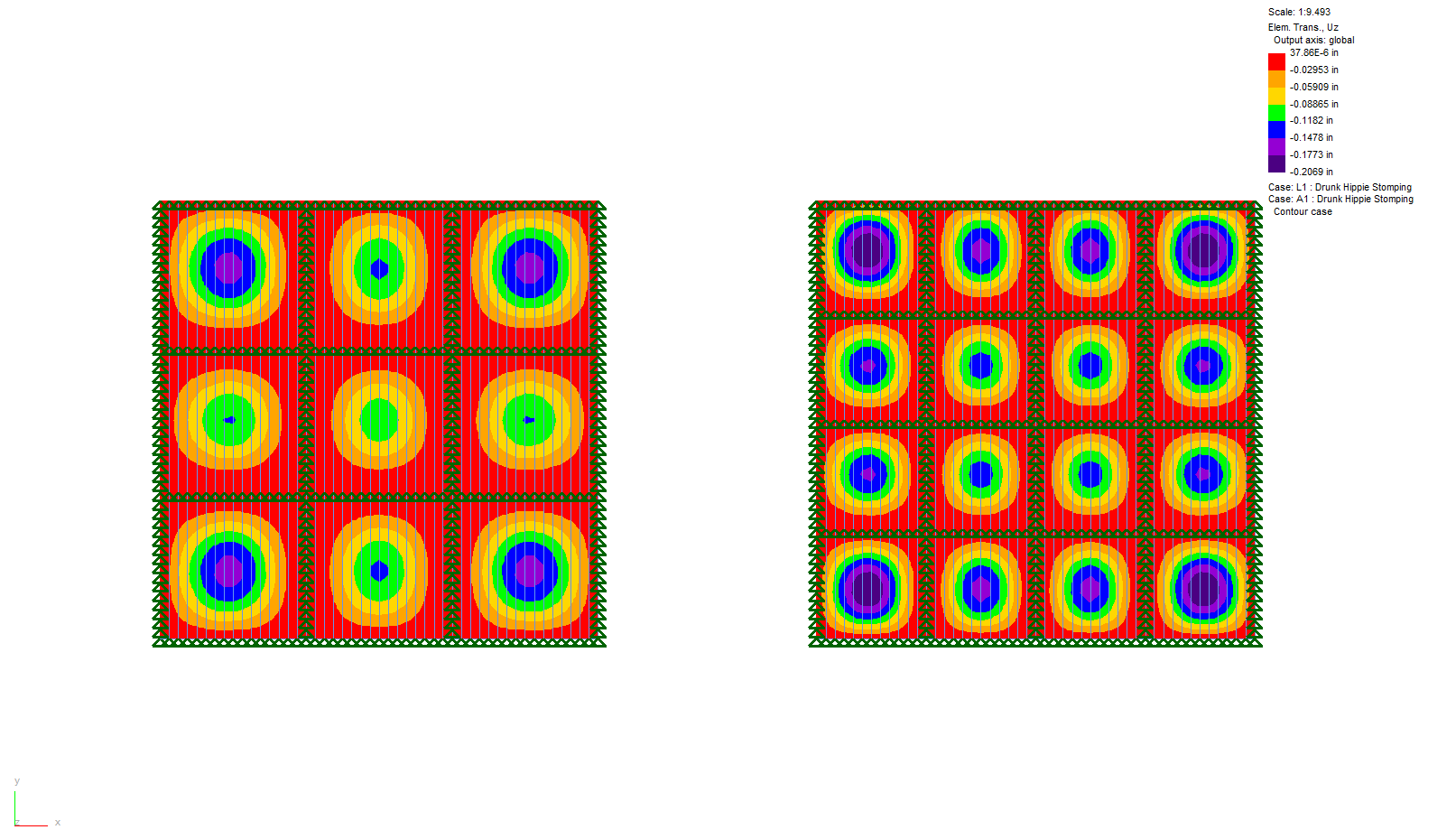
In the end, we're going with 1/2" semi-opaque acrylic over 11" squares. This now increases the number of squares from 81 to 144.
Plastic and the wood base
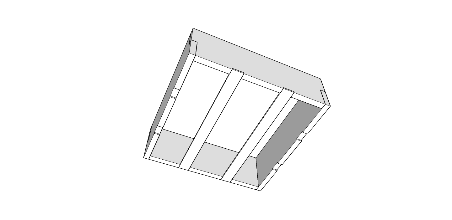
Next was figuring out how to attach the plastic to the wood base. We're still planning to break the floor into 4' x 4' sections, which will hopefully transport well and go together quickly. Each section will have 16 squares underneath it.
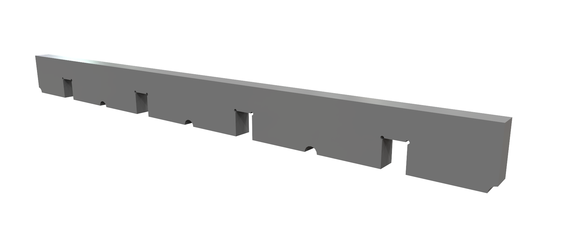
The base will be made of wood ribs that are notched so that they fit together into a grid. The inside ribs will be between 1/2" to 1" thick, with the outside wall being half that, so the border between squares is consistent across the floor.

LEDs
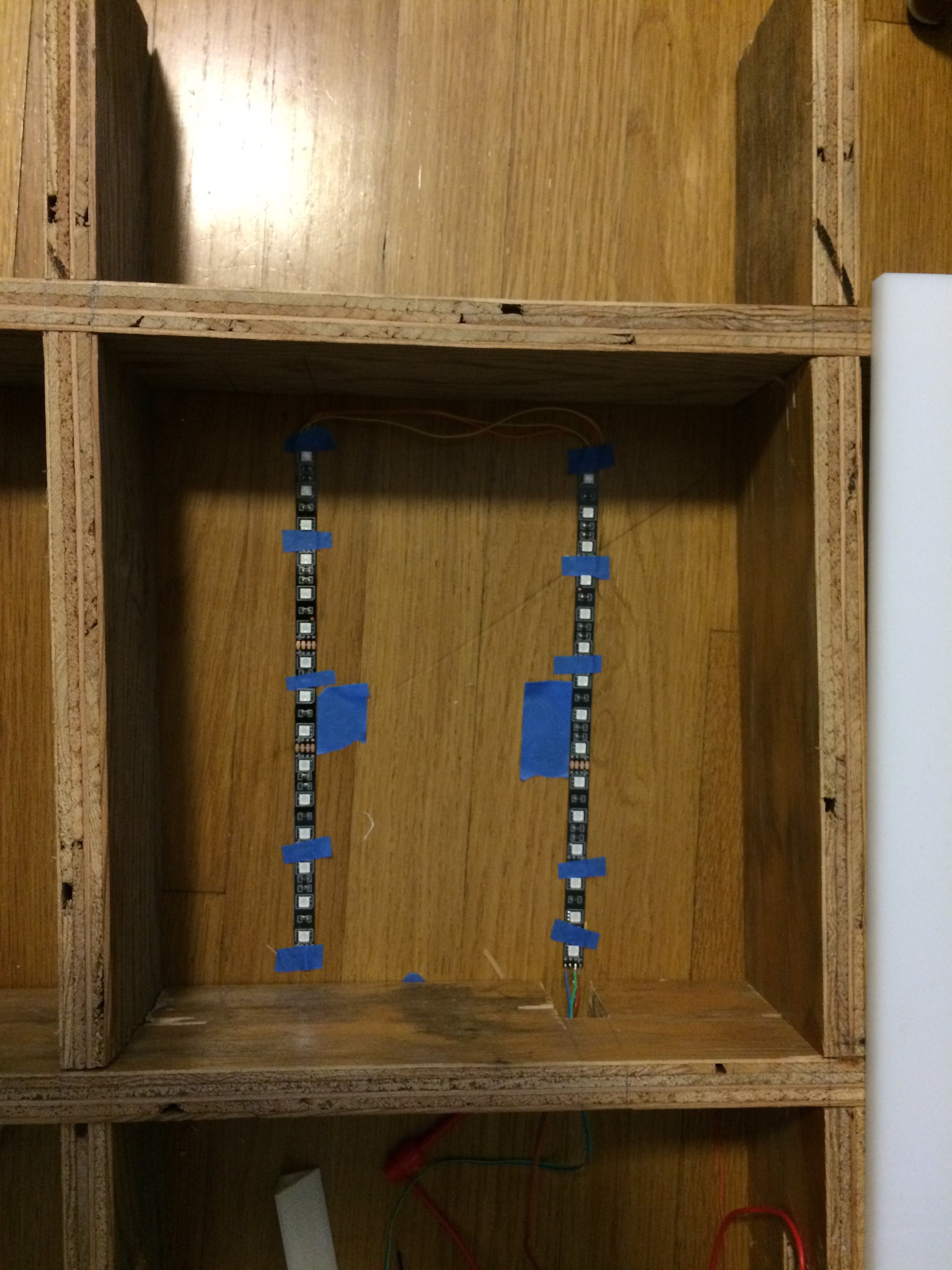
Which brings us to lighting the whole thing. After testing many LEDs and looking at several sources, it seems that using LED strips will be the cheapest and easiest way to go. We built a scale test platform and tested several arrangements. The two options that work the best are:
1. Mounting 1 meter of the LED strip around the perimeter of the box. This uses 1A at max output per square.
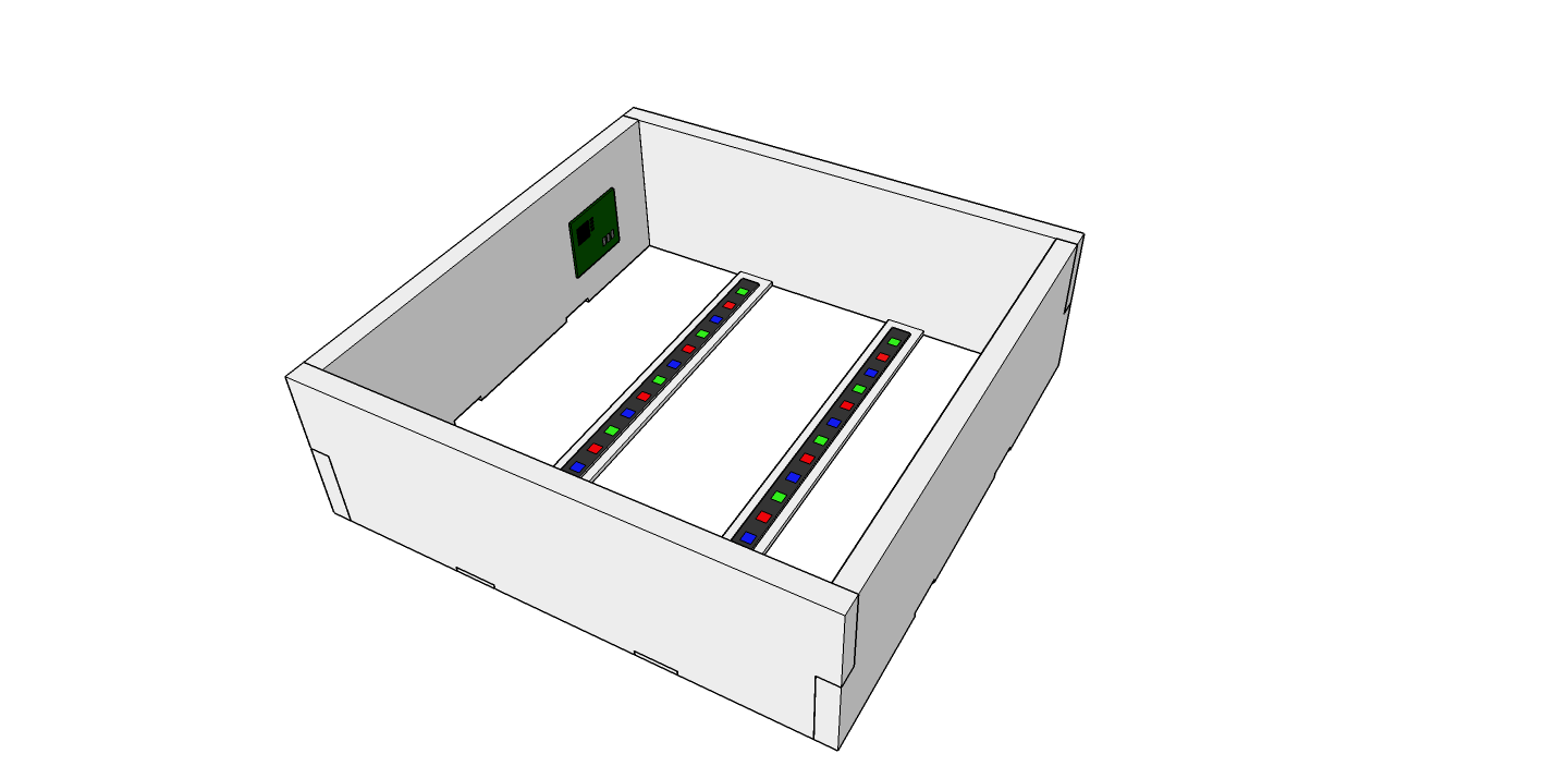
2. Mounting two 25cm strips on the bottom of the box, approximately 3" from the sides. This uses about 500mA at max output per square.
Both options produce approximately the same amount of perceived light through the plastic. The first option is easier to install, but needs twice the amount of juice. So we're going with the option number 2. This means that we'll need to put a couple of thin pieces of wood across the bottom of each square that the LED strips can mount to.

Mylar Reflective Film
I'm about to test what happens if I cover the bottom of the box with a mylar reflective sheet. I'm hoping this will help increase the light output coming through the plastic. My only concern is that it could also turn the squares into mini ovens and damage the electronics and LEDs. I'll have to find a way to test this as well.
Capacitive Sensor
Lastly, in this update is the capacitive sensor.
First, we've found that using chicken wire under the plastic as the sensor area is much more reliable than loops of magnet wire! This is cheap and much easier to setup than figuring out how to attach loops of wire to the underside of the plastic!
We're still using the Arduino CapacitiveSensor library for detecting if a person is standing on a square. This works, however the library requires a blocking action. With a network of 144 nodes, this can block communication and cause some latency issues. I've added some code to try to do the sensing when the node is not responding to the network and master will skip a node if it is taking too long to respond. This helps, but is not perfect. The plan is to write a custom library that will use timers or interrupts, so it will seem to happen in the background.
Next Steps
In the next couple weeks we're going to be finalizing the circuit board design and building the first 4' x 4' section! Stay tuned.
Discussions
Become a Hackaday.io Member
Create an account to leave a comment. Already have an account? Log In.