Close
0%
0%

Single Comparator/Op-Amp[?] Toggle-Flip-Flop

Imagining a pen-clicker, had to test my analogish-skills...

Similar projects worth following
A 5V logic coompatible falling-edge-triggered Toggle-Flip-Flop using a single active component (so far, a comparator. Soon to try an op-amp).
The idea was derived from a pen-clicker... and, surprisingly, it works!

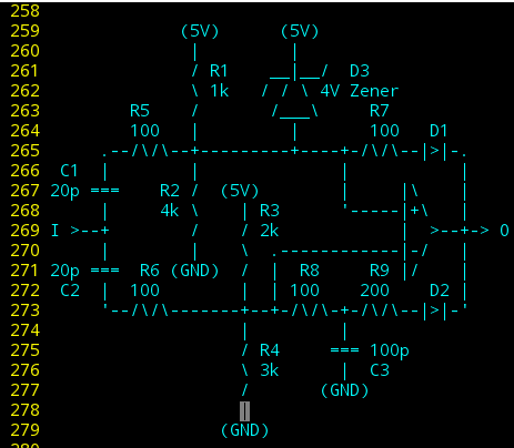
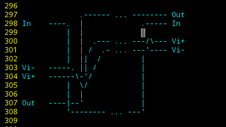
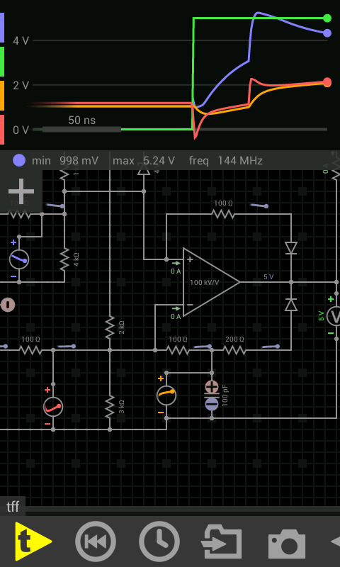
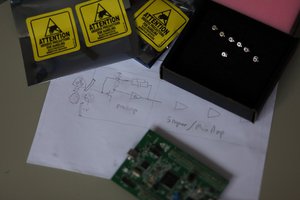
I needed a T-Flip-Flop for my project #Floppy-bird , and didn't have any TTL components on-hand, so I thought I'd see if it was possible with comparators...

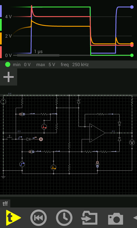
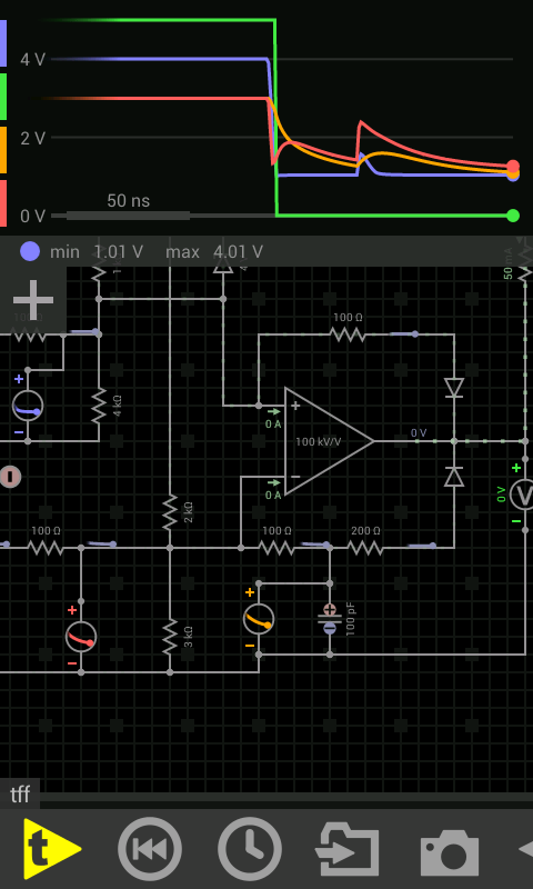
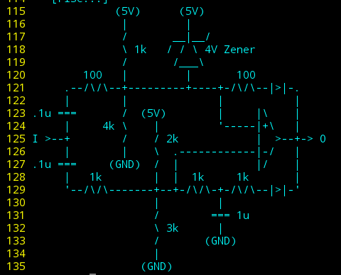
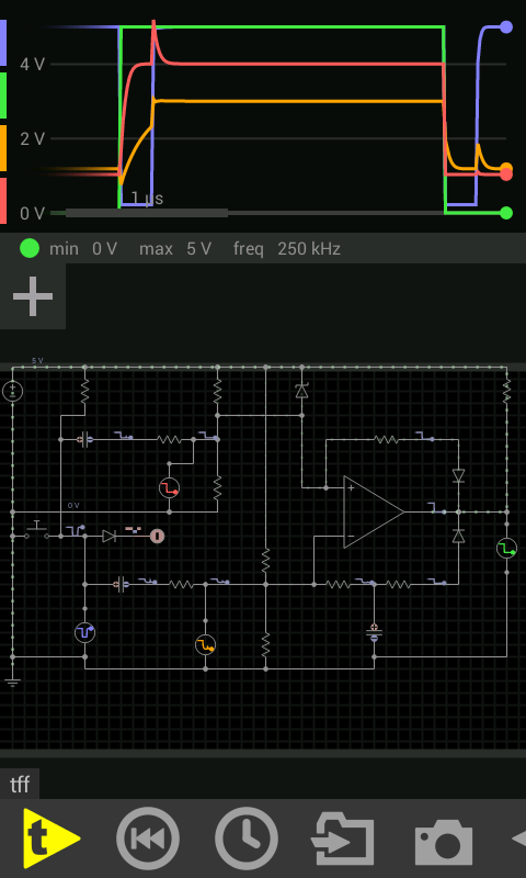
A fellow 'round here has done some interesting stuff with diodes as transistors, and such-like that seems otherwise uncommon, if not "impossible", so inspired by @Ted Yapo, I ventured into the realm of doing-so with only a single comparator. The idea, then, was maybe it'd eventually be possible with a single Transistor...

And, lo-and-behold, roelh's One Transistor FlipFlop. Glad to see it's possible!

  • Op Amp Challenge Accept-ed(?)

    Eric Hertz04/25/2023 at 12:19 2 comments

    I do not at all consider myself good at analog circuitry. It's one of those things that intrigues me conceptually, but has mostly eluded me in the few times I've found the time [and courage!] to try again over the last three decades.

    Thus, seeing mention of the "Analog Challenge"  on The Blog gave me a bit of a forlorn sigh...

    Until it finally came to me...

    Somehow I'd forgotten this project, my proud analog moment of a few years back!

    -------

    This project is rather ridiculous, if you think about the number of transistors involved, and the crazy slew/arrangement of support components. And, I'd kinda prided myself on the fact it involed only one active component, heh! And a zener? Really? Can that be considered "passive?" 

    But, at the time I didn't have my TTL collection with me, so I thought I'd see what could be done with what I had on-hand [What weird stage in my life did I go through when I'd have comparators with me but not TTL?!]

    Progress was also motivated by the thought that maybe someday I could use the same inspiration for this circuit [a pen-clicker] to acheive similar with a single transistor. A fellow Hackadayer beat me to that (link in this project's description), which I actually found to be a bit of a relief, since this design relies heavily on the fast/full-swing switching of a comparator, which surely a single transistor wouldn't provide... 

    ...And, frankly, I'd kinda grown to love the ridiculousness of this circuit's excessive support-circuitry, when a few transistors in a digital 7474-like design could've surely done the job without any "spooky analog" weirdness like slightly-differing capacitor-charging delays or voltage-dividers outputting only slightly different values, or a friggin voltage-regulator, heh! And, frankly, how much more sophisticated, internally, a comparator is than a few NAND gates. 

    And to think, it actually worked; this crazy analog design from a guy who had had little other than bad luck in decades of attempts designing analog!

    ...

    Hmmm...

    So, what about an Op-Amp?

    I mean, they're just comparators with lower gain and larger delays, right? Albeit, internally even more complicated and precise... Further adding to this project's appealing ridiculosity...

    Challenge Accepted.

    Maybe I'll luck-out and it's a simple drop-in replacement[?]. But, as part of my own added challenge, I think I'll again attempt this with parts on-hand. Which basically amounts to LM-series from the 80's. We'll See!

  • VID

    Eric Hertz04/16/2018 at 00:49 7 comments

    Here it is, in all its glory!

    First, the audio is converted to PWM.

    Then both PWM edges are converted to falling-edge pulses.

    This, then, could be fed directly into a floppy drive's "write data" input, storing the PWM on-disk.

    When read-back from the disk, the floppy drive will give these same falling-edge pulses to indicate each edge of the recorded PWM.

    That, then, gets fed into my single-comparator T-Flip-Flop, to convert those falling-edges back into PWM, then directly drives a speaker.

    ----------

    Ahh, right... So, this video was recorded months ago... long before I ran the 500KHz simulations. I can't recall the frequency this is running at, but it's surely slower than 500KHz, otherwise, as my conclusions, after running the sims... concluded... This system probably won't run at 500KHz, with the LM311's I used.

    I do have faster (2ns!) comparators in the ol' storage-unit... but haven't really decided to go that route, much easier to use a 7474... and, realistically, I only need 500KHz for the *image* portion of #Floppy-bird, which wouldn't benefit from a T-FF at all, being that it'd still have to go into the uC for processing...

    However, (wee, look at this link go!) it would be an interesting thing to try, some day, maybe... 500KHz...

  • 500khz components, explanation

    Eric Hertz01/27/2018 at 02:39 2 comments

    here's the components determined in the sims....

    R1-4 are two voltage-dividers to bias Vi+ at 4V and Vi- at 3V. Thus, when the comparator is off and no toggling occurs at the input, the comparator's output is high (well, the LM311 is open-collector/Hi-Z... and, confusingly, I've the habit of calling it "off" when Vi+ > Vi-, and "on" when the output is low).

    So... it remains "off" as-biased... 4V > 3V.

    A pull-up resistor is not shown on the output... but it's unnecessary for this circuit, only for those following,

    D1 and D2 isolate the output's feedback-paths to Vi+ and Vi-, so's we don't have to consider each's present voltage on the other (especially when the output is Hi-Z).

    R7 and the Zener diode form a crude voltage-regulator. Thus, when the comparator output is low, Vi+ will be pulled to ~1V.

    When the comparator is on, the zener also prevents the next falling-edge input from dropping Vi+ lower than Vi-. It essentially keeps Vi+ from seeing that falling edge.

    (I imagine the zener could be replaced with cleverer resistor usage, but... Math! I'm not so great with analog circuits, it always seems every 'building-block' thrown in has a dramatic effect on all the others. Here, I'm attempting to reduce that effect. Thus diodes, and AC-coupling.)

    So, now, Vi+ has two steady-states; 3V and 1V.

    The feedback-path for Vi- is slightly more complicated. R9 and C3 limit the rate that Vi- is affected by the comparator's turning on (and off). Similarly, R8 and, again, C3 cause input-edges to be smoothed slightly before entering Vi-. 

    Thus, the comparator turns on, latching Vi+ low when the present value of Vi+ is lower than the *previous* value of Vi-.

    (But wait! That's wrong! So it *does* still function as I originally planned, the spike on Vi+ is larger than that on Vi-, but still simultaneous, so they cross... huh. No.. wait, these don't even look the same. Sheeit. Now I remember why a short lab-report always took HOURS longer than seemingly anyone else's took them.)


    But, again, Vi+ essentially doesn't see the next falling-edge, so that slight delay from C3 doesn't stop that edge from bringing Vi- below the steady Vi+, turning the comparator off, again.

    Now, as for the rising-edges on the input...

    If the two paths were identical, both inputs would rise, briefly, together, and so wouldn't cross-over. Thus, there'd be no change as far as the comparator is concerned...

    But of course, the two paths differ (otherwise the same would be true for falling edges, and nothing would happen, ever). So... I didn't really put a huge amount of thought into the rising edge... Instead, some early values for R8 and 9 led to the "on" steady-state voltages for Vi+ and Vi- to be "too close for comfort", so I tweaked those values so that Vi- would be dramatically lower, in that state... nearly half a volt. R6 was initially chosen to be higher than R5 so that the spikes on Vi- would be smaller than those on Vi+, but this is where the progression led me, during simulation.

    (BTW, when I was in school, running a simulation meant setting up the circuit, clicking 'run' and waiting several minutes. Now it's possible to do sims in 'real-time', wherein you can change component values while simulating. Very handy.)

    Here were my original proof-of-concept component choices:

    And, again, those after experimenting:

    (It may be possible to remove the feedback path to Vi-, altogether. The...

    Read more »

  • Sims

    Eric Hertz01/26/2018 at 03:51 0 comments

    i've done 'em before, but not at my desired speeds...  I'm planning roughly 500khz for another project. Also, I didn't look closely at the edges,

    I usually use Paul Falstad's online simulator, but it doesn't work so well on this phone, so branched out for a (woo, 24-hour...) trial of EveryCircuit. Seems pretty good, but not in my budget.

    So, new component values. But looks like it should work great!

    Then... I remembered that the LM311 I plan to use has a delay of 200ns.... erm.

    So tried to simulate that... and it *dramatically* slows the toggle-frequency. Nevermind my source guarantees low-pulses down to 0.1us.

    Also, not certain it'd still function with more real-world slew-rates at the input.

    But, I'm still pretty content with this /wonky idea's functioning at all!

View all 4 project logs

Enjoy this project?

Share

Discussions

Similar Projects

Does this project spark your interest?

Become a member to follow this project and never miss any updates