 Eric Hertz
here's the components determined in the sims....
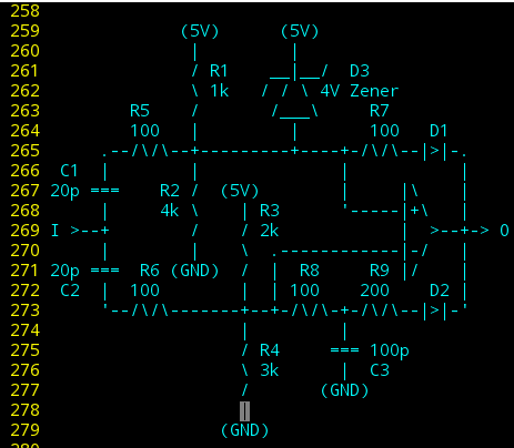
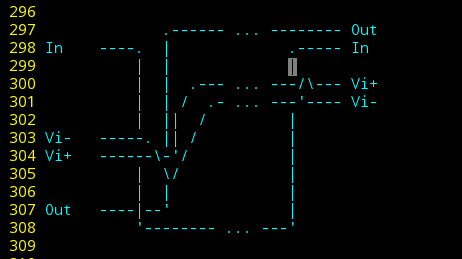
R1-4 are two voltage-dividers to bias Vi+ at 4V and Vi- at 3V. Thus, when the comparator is off and no toggling occurs at the input, the comparator's output is high (well, the LM311 is open-collector/Hi-Z... and, confusingly, I've the habit of calling it "off" when Vi+ > Vi-, and "on" when the output is low).
So... it remains "off" as-biased... 4V > 3V.
A pull-up resistor is not shown on the output... but it's unnecessary for this circuit, only for those following,
D1 and D2 isolate the output's feedback-paths to Vi+ and Vi-, so's we don't have to consider each's present voltage on the other (especially when the output is Hi-Z).
R7 and the Zener diode form a crude voltage-regulator. Thus, when the comparator output is low, Vi+ will be pulled to ~1V.
When the comparator is on, the zener also prevents the next falling-edge input from dropping Vi+ lower than Vi-. It essentially keeps Vi+ from seeing that falling edge.
(I imagine the zener could be replaced with cleverer resistor usage, but... Math! I'm not so great with analog circuits, it always seems every 'building-block' thrown in has a dramatic effect on all the others. Here, I'm attempting to reduce that effect. Thus diodes, and AC-coupling.)
So, now, Vi+ has two steady-states; 3V and 1V.
The feedback-path for Vi- is slightly more complicated. R9 and C3 limit the rate that Vi- is affected by the comparator's turning on (and off). Similarly, R8 and, again, C3 cause input-edges to be smoothed slightly before entering Vi-.
Thus, the comparator turns on, latching Vi+ low when the present value of Vi+ is lower than the *previous* value of Vi-.
(But wait! That's wrong! So it *does* still function as I originally planned, the spike on Vi+ is larger than that on Vi-, but still simultaneous, so they cross... huh. No.. wait, these don't even look the same. Sheeit. Now I remember why a short lab-report always took HOURS longer than seemingly anyone else's took them.)
But, again, Vi+ essentially doesn't see the next falling-edge, so that slight delay from C3 doesn't stop that edge from bringing Vi- below the steady Vi+, turning the comparator off, again.
Now, as for the rising-edges on the input...
If the two paths were identical, both inputs would rise, briefly, together, and so wouldn't cross-over. Thus, there'd be no change as far as the comparator is concerned...
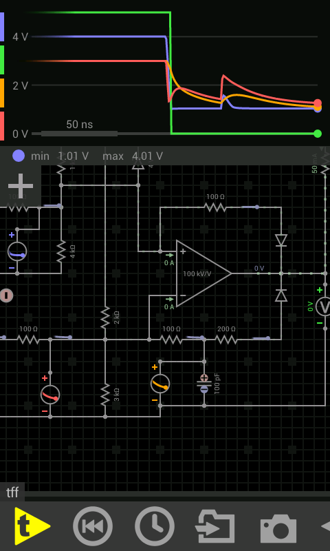
But of course, the two paths differ (otherwise the same would be true for falling edges, and nothing would happen, ever). So... I didn't really put a huge amount of thought into the rising edge... Instead, some early values for R8 and 9 led to the "on" steady-state voltages for Vi+ and Vi- to be "too close for comfort", so I tweaked those values so that Vi- would be dramatically lower, in that state... nearly half a volt. R6 was initially chosen to be higher than R5 so that the spikes on Vi- would be smaller than those on Vi+, but this is where the progression led me, during simulation.
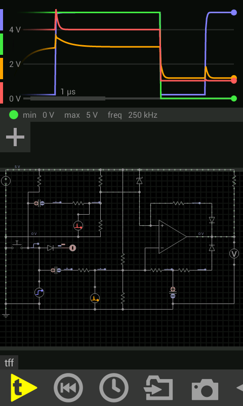
(BTW, when I was in school, running a simulation meant setting up the circuit, clicking 'run' and waiting several minutes. Now it's possible to do sims in 'real-time', wherein you can change component values while simulating. Very handy.)
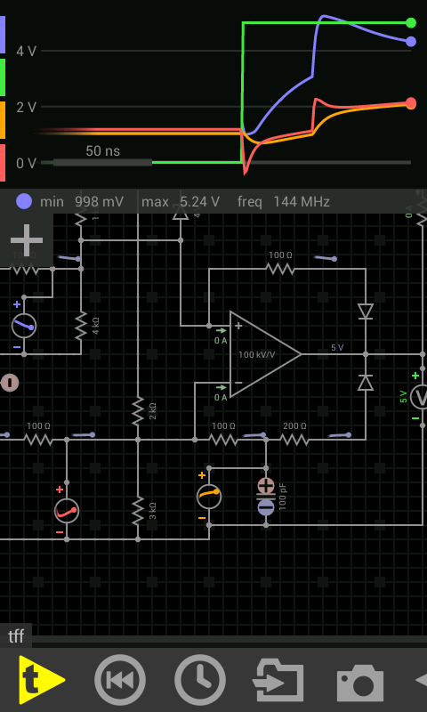
Here were my original proof-of-concept component choices:
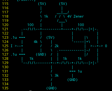
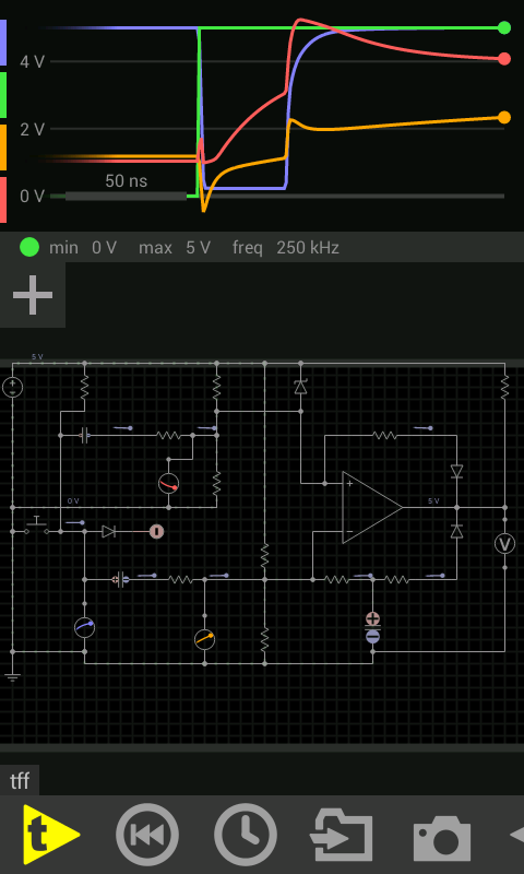
And, again, those after experimenting:
(It may be possible to remove the feedback path to Vi-, altogether. The original intent was to bring its value close to Vi+ at 1V, so the *smaller* spike on Vi- would cross-over the steady Vi+. That may be less relevant now that both inputs use the same capacitances and resistances... hmmm...)
Some choices and changes were definitely random experimentation, but certainly most were more thoughtful... input capators, T=RC... the "1-to-ten rule"... throw in some rough estimates with some rough expectations, tweak accordingly.
OTOH: sims are not reality... a prime example being my intended use of an LM311... this guy has a response-time of 200ns. But the widths of my negative-pulses are as short as 100ns, latching never occurs. The comparator (op-amp, actually) in the sims responds immediately. Whoops. I do have faster comparators, but this was more a proof of concept based on parts at-hand than a necessity. I also have 7474's. Done.
OTOOH, leads me to wonder if a flip-flop can be designed with a single transistor.
Also, I swear I saw some sims where a negative input-pulse caused a positive pulse... something to do with diodes' capacitances, maybe? Or maybe just the switching of the comparator. But, the comparator doesn't pull-up, and why would it bounce back down...? (Red line at falling edge of blue). Reminded of @Ted Yapo 's diode-inverters.
DAGNABBIT *NO*!!!
I spent a LOT of time considering the rising edge when I designed this month(s?) ago. How could I have forgotten?!
Discussions
Become a Hackaday.io Member
Create an account to leave a comment. Already have an account? Log In.
heck, the whole point of R8 was to isolate the spikes from C3, so they *would* come through, unimpeded!
Are you sure? yes | no
friggin' *countless* designs, keeping the friggin' rising edge in mind. Heck, one design used the falling edge to latch on and the *second* rising edge to latch off. SHEESH, Brain!
Are you sure? yes | no