 Jose Ignacio Romero
[December 28, 2014]
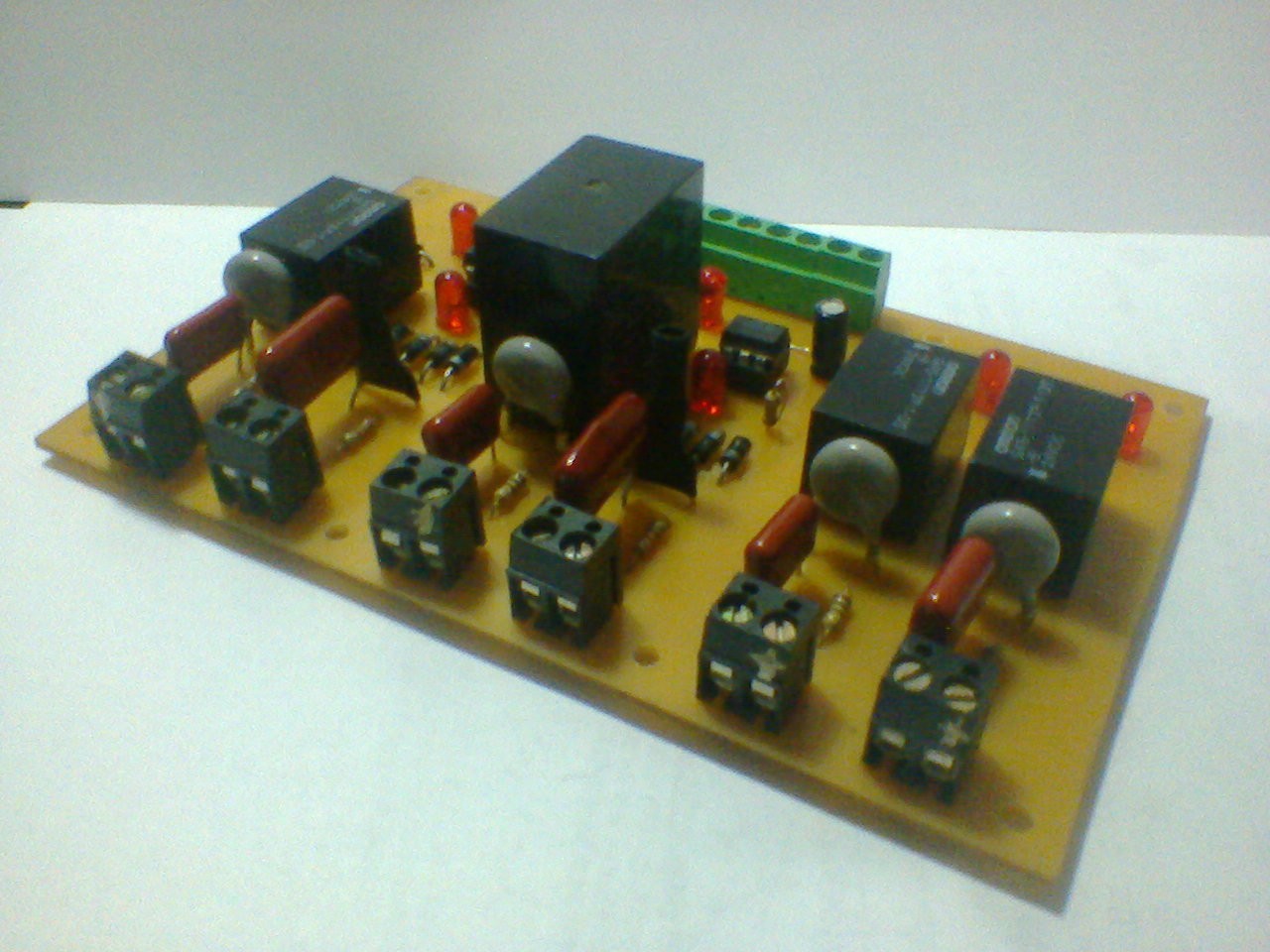
I designed and built the "power" board of the machine first because I felt that was the most challenging thing to get right. I took great care to respect the current ratings of every element and clearance/creepage distances since this board would interface my 24V logic with 220V mains stuff.
An unpleasant surprise I found while disassembling the machine is that two signals I thought would be dry contacts actually are single ended 220v mains signals coming from the control element. Namely, the door locker and the thermostat "ready" signal. Since those two signals are very important and there's no easy way to wire them with 24VDC I designed an optocoupled interface circuit that would take the 220V signal and activate a standard NPN output for my 24V PLC input stage.
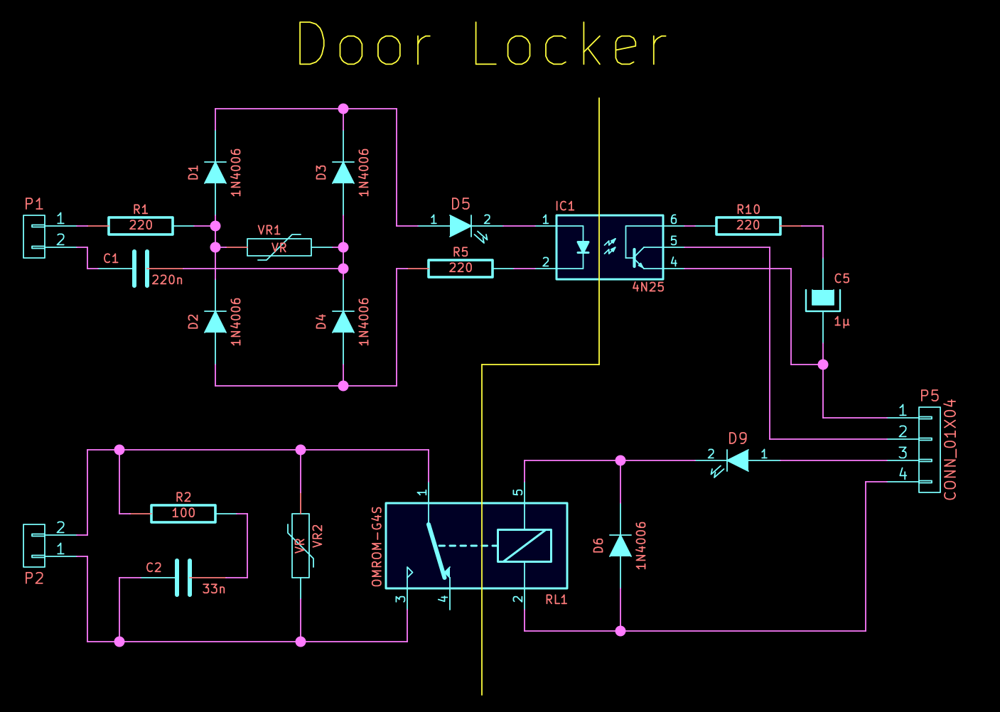
I don't claim this design to be super innovative, but I did combine several ideas I saw in other industrial circuits. The 220VAC signal enters P1 and has to go through R1 and C1 to get to the bridge rectifier formed by D1, D2, D3, and D4, which in turn feeds D5 (LED) and IC1 (optocoupler).
R1 and C1 have an impedance of ~16kΩ for 220VAC@50Hz, which would limit the RMS current through the LEDs to around 13mA, VR1 is actually a 10V TVS diode in the final board. It's function is to absorb high frequency spikes that would go right through C1 and cause big current spikes since a capacitor's impedance falls with frequency. In theory the 10V clamp would limit the worst case current spike through the LEDs to less than 30mA, which is fairly safe.
Due to the bridge rectifier action, the LED and optocoupler will stay on for most of the signal's cycle, except for brief instants around the zero crossing point of the signal where the voltage drops below ~6 volts. Those short drops would show up as low duty cycle 100Hz pulses in the output. To get rid of those I needed a low pass filter. At first I thought about adding a couple transistor stages with the filter in the middle, but then I realized I could hack a low pass filter with the opto itself. I did that by adding base capacitance to the output transistor. I simulated the circuit with LTspice and tuned the R and C values to give a decent response. The circuit worked as designed first go.
The relay part is fairly unremarkable, it has a standard RC snubber and MOV to protect the contacts. The only hack-y part is the way I connected the LED to save parts and power. Since the relay has a DC resistance of around 4kΩ, connecting it in series provided enough current to brightly light it. Connecting the LED with a 4k7 resistor in parallel with the coil would have burned as much power in the ballast resistor as the relay itself!
Note: The optocoupler circuit should work unmodified for 120VAC@60Hz, since the C1+R1 impedance would then be ~13k5 which would limit the current to ~8.5mA, it's best to optimize the components for the line voltage in question, though. Oh, and I didn't just use a 15k resistor there because that would dissipate 3W, which I felt would be too wasteful, and an annoying amount of heat to get rid of!
Discussions
Become a Hackaday.io Member
Create an account to leave a comment. Already have an account? Log In.