 agp.cooper
What is polling?
If you have uploaded the example "Blink without delay" sketch then you have used polling:
// Blink without delay
void setup() {
  pinMode(LED_BUILTIN,OUTPUT);
  digitalWrite(LED_BUILTIN,LOW);
}
void loop() {
  static unsigned long previousMillis=0;
  unsigned long intervalMillis=1000;
  unsigned long currentMillis;
  // Toggle LED when time interval is up!
  currentMillis=millis();
  if (currentMillis-previousMillis>=intervalMillis) {
    previousMillis = currentMillis;
    digitalWrite(LED_BUILTIN,!digitalRead(LED_BUILTIN));
  }
}
Polling just checks your input switches regularly to determine if something has changed. In the "Blink without delay" example, the millis counter is polled until one second (i.e. 1000ms) has passed. At this time the LED state is inverted (i.e. toggled).
The Ticker library does this more succinctly:
#include "Ticker.h"
// The Blink routine
void Blink() {
  digitalWrite(LED_BUILTIN,!digitalRead(LED_BUILTIN));
}
// Create a timer
Ticker timer1;
void setup() {
  pinMode(LED_BUILTIN, OUTPUT); // Initialise the Ticker
  timer1.setCallback(Blink);    // Set timer1 function to Blink()
  timer1.setInterval(1000);     // Set timer1 interval to 1000 ms
  // start the Ticker
  timer1.start();
}
void loop() {
  // Update the Ticker
  timer1.update();
}
With the Ticker example a "timer" (i.e. a Ticker) has been set up to toggle the LED every 1000ms.
Not polling but an interrupt service routine
Another way is to use a real timer and an interrupt service routine (ISR):
volatile unsigned int magic=0;
ISR(TIMER2_OVF_vect) {
  static unsigned int phase=0;
  if (phase<0x8000) {
    phase+=magic;
    if (phase>=0x8000) {
      digitalWrite(LED_BUILTIN,LOW);  // LED on
    }
  } else {
    phase+=magic;
    if (phase<0x8000) {
      digitalWrite(LED_BUILTIN,HIGH); // LED off
    }
  }
}
void setup() {
  // LED pinMode(LED_BUILTIN,OUTPUT);
  // Use Timer 2 for ISR
  // Good for ATmega48A/PA/88A/PA/168A/PA/328/P
  cli();
  TIMSK2=0;                                  // Clear timer interrupts
  TCCR2A=(0<<COM2A0)|(0<<COM2B0)|(3<<WGM20); // Fast PWM
  TCCR2B=(1<<WGM22)|(2<<CS20);               // 2 MHz clock and (Mode 7)
  OCR2A=243;                                 // Set for 8197 Hz
  OCR2B=121;                                 // Not used
  TIMSK2=(1<<TOIE2)|(0<<OCIE2A)|(0<<OCIE2B); // Set interrupts
  sei();
  // Update frequency without interrupt
  // Note freq should be between 1 and 4095
  unsigned int freq=1;
  cli();
  // magic=(freq<<3); // magic=freq/8
  magic=4; // 0.5Hz
  sei();
}
void loop() {
}
Now the ISR was truely awful as far as readable code! And I had to use a timer. The above code came from my Midi project. The timer frequency is programmable over a wide range and thus a bit more complicated than usual.
A better way to use timers and interrupts is to use a library like TimerOne:
#include <TimerOne.h>

void setup(void) {
  pinMode(LED_BUILTIN,OUTPUT);
  Timer1.initialize(1000000); // 1s
  Timer1.attachInterrupt(Blink);
  Serial.begin(9600);
  delay(200);
  Serial.println(TIMSK0,BIN);
}

void Blink(void)
{
  digitalWrite(LED_BUILTIN,!digitalRead(LED_BUILTIN));
}
void loop(void) {

}
Here the timer "polling" period is programmable in microseconds (except the accuarcy is probably 2-4us.
A free ride!
Why not use the millis timer (i.e. timer0)?
Checking the interrupt timer register, I find only the overflow interrupt (TOIE0) has been used. This leaves OCIE0B and OCIE0A free for use (subject to being mindful of the millis ISR execution time requirements and not using PWM on pins 5 and 6).
Notes:
- Timer0 is an 8 bit timer and the prescaler is 1/64 (i.e. the clock is 250kHz).
- The overflow count is 255 so the timer interrupt interval is 1024us, not 1000us.
We can create a custom millis and seconds timer as shown below:
// Custom Clock ISR
volatile unsigned long clockTics=0;
ISR(TIMER0_COMPA_vect) {
  static long clockMillis=0;
  static long clockAdj=0;    // Seconds per day counter
  static long magic=2074+18; // Add 18 seconds per day
  // Timer0 overflow period is 1024us (=256*4us)
  clockMillis++;
  clockAdj+=magic;
  if (clockAdj>=86400) {
    clockAdj-=86400;
    clockMillis++;
  }
  // Update second clock
  if (clockMillis>=1000) {
    clockMillis=0;
    clockTics++;
  }
}
This custom timer adds 18 seconds a day to the clock, as the particular Nano runs too slow by about 18 seconds a day.
To activate the custom timer we need to add the following lines to setup() routine:
 /* Set my millis timer */
 // Use the millis() interrupt (Timer0) without upsetting anything
 // Call COMPA interrupt in the middle of the count
 OCR0A=0x80;
 TIMSK0|=1<<OCIE0A;
How to poll efficiently
What does efficiently mean? Okay, here is how I did it and I will leave it to you to decide if it is efficient.
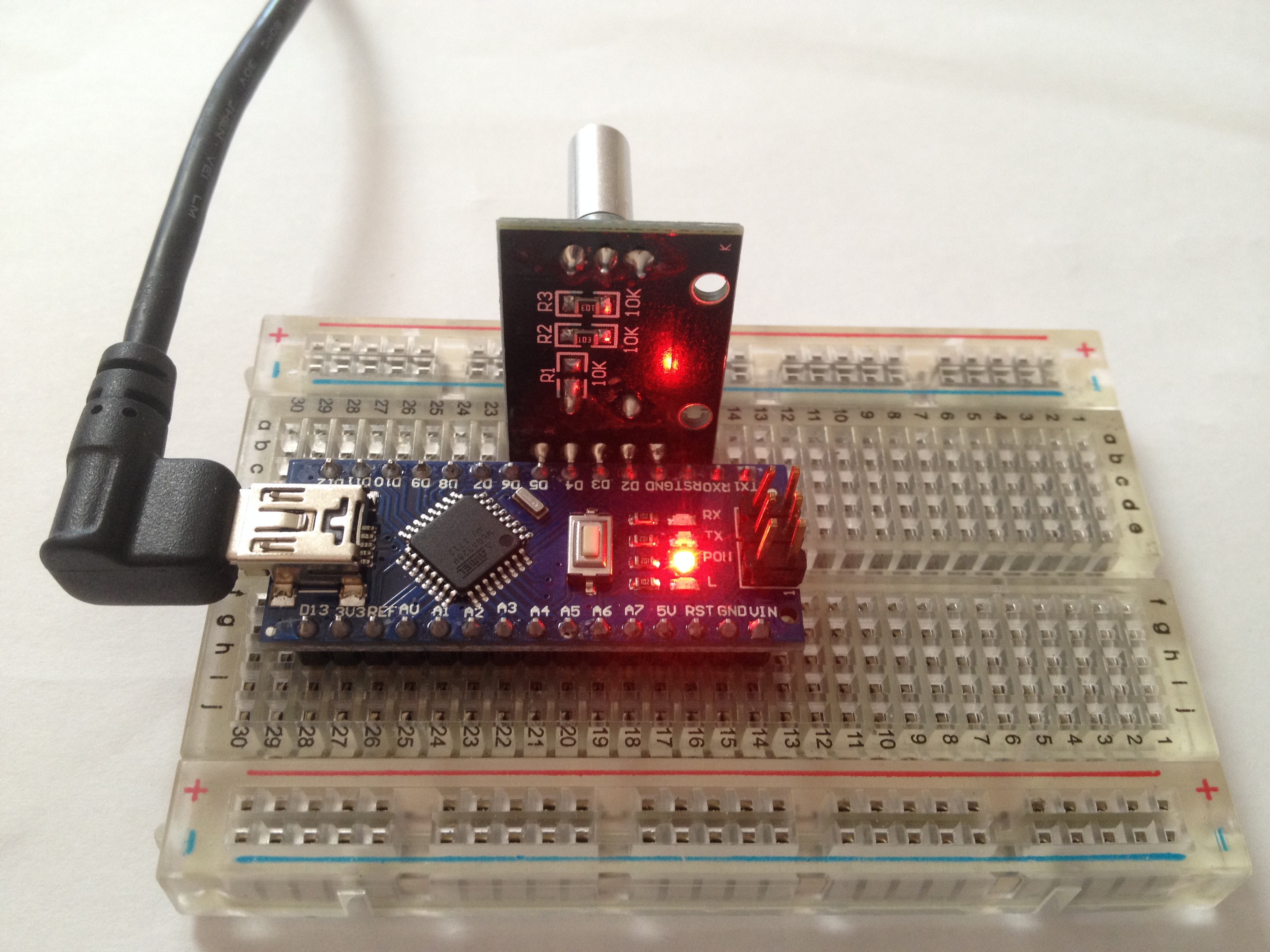
Scope
Interface to a rotary encoder with a push button switch.
Here is the test setup:
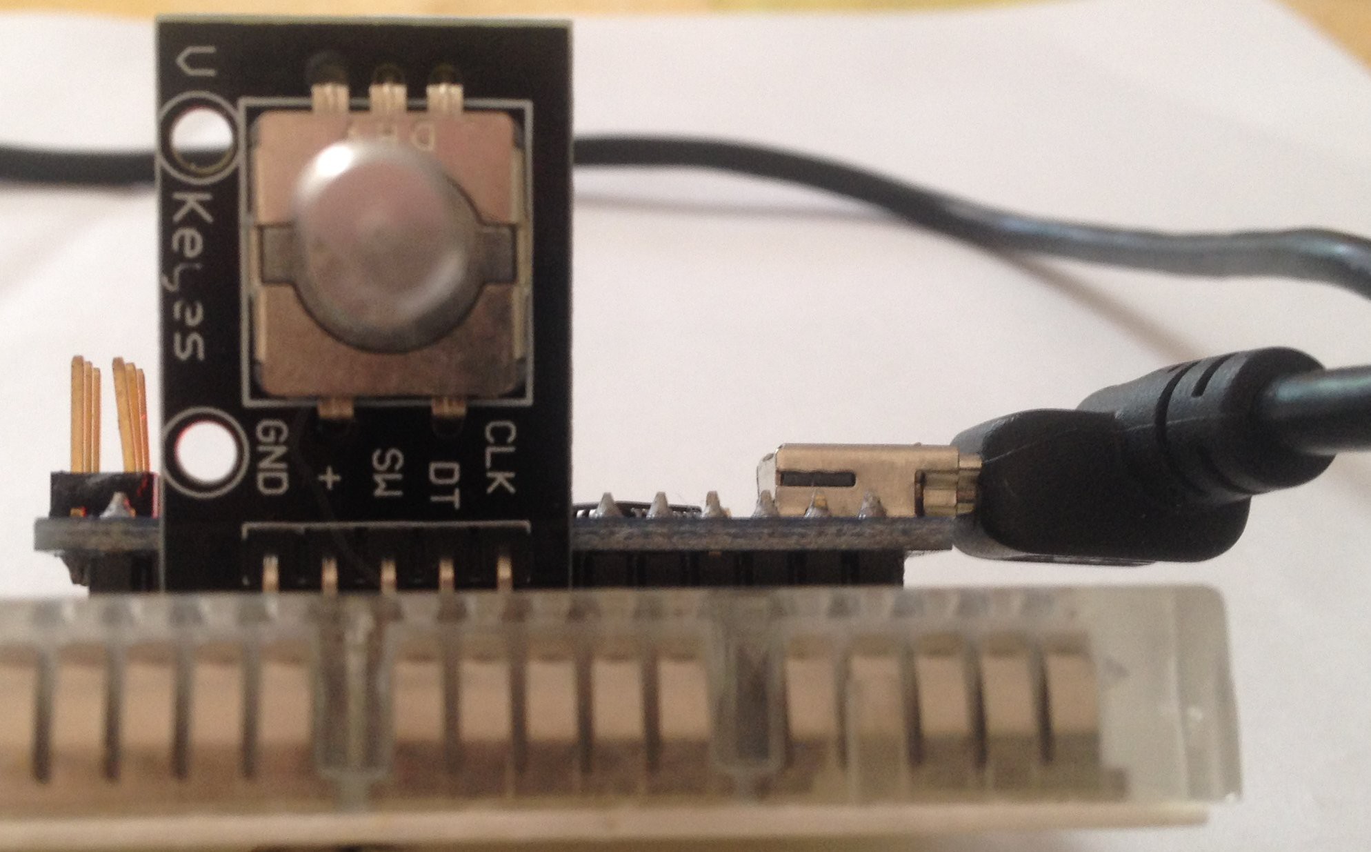
And here is the reverse side:
Push button code
Here is my code for polling and debouncing the push button switch:
// Poll and debounces a push button switch:
#define SW  3 // The switch has no pull up resistor
// Exports:
//   UpdateSwitch (bool)   [true|false]
//   Switch (byte)         [LOW|HIGH]
volatile bool UpdateSwitch=false;
volatile byte Switch=HIGH;
ISR(TIMER0_COMPA_vect) {
  static byte testSW=HIGH;
  static byte statusSW=HIGH;
  static byte cntSW=0;

  // Update switch with 10ms debounce
  testSW=(PIND>>SW)&1;
  if (testSW!=statusSW) {
    statusSW=testSW;
    cntSW=10;
  }
  // Count down 10ms
  if (cntSW>0) {
    cntSW--;
    if (cntSW==0) {
      Switch=statusSW;
      UpdateSwitch=true;
    }
  }
}
void setup() {
  // A switch without a pullup resistor
  pinMode(SW,INPUT_PULLUP);

  // Turn on the polling ISR
  OCR0A=0x80;
  TIMSK0|=1<<OCIE0A;

  // Use the LED to indicate that the button has been pushed
  pinMode(LED_BUILTIN,OUTPUT);
  digitalWrite(LED_BUILTIN,LOW); // Turn off LED
}
void loop() {
  // If push button pushed/released
  if (UpdateSwitch) {
    UpdateSwitch=false;
    if (Switch==LOW) {
      digitalWrite(LED_BUILTIN,HIGH); // Turn on LED
    } else {
      digitalWrite(LED_BUILTIN,LOW);  // Turn off LED
    }
  }
}
The above code polls a switch to check if it has changed state. If the button changes stata then a 10ms counter is started. When it expires (if not restarted), a status flag (UpdateSwitch) and the switch value (Switch) are set.
Rotary encode code
If coded correctly the rotary encoder switches do not need debounce. Here is my polling code for a rotary encoder:
#define Clk 5
#define DT  4
// Poll a Keyes rotary switch
// Inputs:
//   Clk (Pin A)
//   DT  (Pin B)
// Exports:
//   EncoderPos (char) [-128..127]
volatile char EncoderPos=0;
ISR(TIMER0_COMPA_vect) {
  static byte testClk=(PIND>>Clk)&1;
  static byte testDT=(PIND>>DT)&1;
  static byte lastClk=LOW;
  static byte lastDT=LOW;
  static bool flagClk=false;
  static bool flagDT=false;
  static char encoderDir=0;

  // Update Encoder Position
  lastClk=testClk;           // Save Clk
  lastDT=testDT;             // Save DT
  testClk=(PIND>>Clk)&1;     // Get Clk
  testDT=(PIND>>DT)&1;       // Get DT
  if (testClk!=lastClk) {    // Change in Clk?
    flagClk=true;            // Flag Clk has changed
    encoderDir=-1;           // Assume it is the last flag to change
  }
  if (testDT!=lastDT) {      // Change in DT?
    flagDT=true;             // Flag DT has changed
    encoderDir=1;            // Assume it is the last flag to change
  }
  if (flagClk&&flagDT) {     // Both flags have changed
    EncoderPos+=encoderDir;  // Update the encoder
    flagClk=false;           // Reset Clk flag
    flagDT=false;            // Reset DT flag
  }
}

void setup() {
  // Keyes rotary encoder
  pinMode(Clk,INPUT_PULLUP); // Rotary Clk (has 10k pullup)
  pinMode(DT,INPUT_PULLUP);  // Rotary DT  (has 10k pullup)
  // The input_pullups are fine providing the rotary encode
  // does not have its own. In this case we need to power them.
  pinMode(2,OUTPUT);         // Rotary + (supply power to encoder)
  digitalWrite(2,HIGH);      // Turn on power for rotary encoder

  // Turn on polling
  ISR OCR0A=0x80;
  TIMSK0|=1<<OCIE0A;

  Serial.begin(9600);
  while (!Serial);

  Serial.println("Rotary Encoder");
  Serial.println(EncoderPos,DEC);
}

void loop() {
  static char lastPos=0;
  // If encoder turned
  if (lastPos!=EncoderPos) {
    lastPos=EncoderPos;
    Serial.println(EncoderPos,DEC);
  }
}
How does the rotary encode code work?
- A rotary encoder has two switches "A" and "B".
- At rest (i.e. detent) the encoder switches will be either both open (high) or both closed (low).
- When rotated clockwise, switch "A" will change state before switch "B".
- When rotated ant-clockwise, switch "B" will change state before switch "A".
- To determine the encoder rotation direction we need to determine which switch changed last and increment or decrement the position variable according.
Note, on the Keyes rotary encoder, the switch "A" pin is call "CLK" and the switch "B" pin is called "DT". Both these switches have 10k pullup resistors that need to be powered via the "+" pin. The pullup resistors are slightly annoying as Arduino's internal pullups are too weak to over come them. You have to power the Keyes rotary encoder. In my sketch I use D2 to power the "+" pin.
Combining the code
Here is the final polling code for the push button and the rotary encoder:
#define Clk 5
#define DT  4
#define SW  3
// Poll and debounce a Keyes rotary and push button switch
// Inputs:
//   Clk (Pin A with 10k pullup resistor)
//   DT  (Pin B with 10k pullup resistor)
//   SW  (Switch without a pullup resistor)
//   +   (Power for pullup resistors)
//   Gnd
// Exports:
//   UpdateSwitch (bool)   [true|false]
//   Switch (byte)         [LOW|HIGH]
//   EncoderPos (char)     [-128..127]
volatile bool UpdateSwitch=false;
volatile byte Switch=HIGH;
volatile char EncoderPos=0;
ISR(TIMER0_COMPA_vect) {
  static byte testClk=(PIND>>Clk)&1;
  static byte testDT=(PIND>>DT)&1;
  static byte lastClk=LOW;
  static byte lastDT=LOW;
  static bool flagClk=false;
  static bool flagDT=false;
  static char encoderDir=0;
  static byte testSW=HIGH;
  static byte statusSW=HIGH;
  static byte cntSW=0;

  // Update Encoder Position
  lastClk=testClk;            // Save Clk
  lastDT=testDT;              // Save DT
  testClk=(PIND>>Clk)&1;      // Get Clk
  testDT=(PIND>>DT)&1;        // Get DT
  if (testClk!=lastClk) {     // Change in Clk?
    flagClk=true;             // Flag Clk has changed
    encoderDir=-1;            // Assume it is the last flag to change
  }
  if (testDT!=lastDT) {       // Change in DT?
    flagDT=true;              // Flag DT has changed
    encoderDir=1;             // Assume it is the last flag to change
  }
  if (flagClk&&flagDT) {      // Both flags have changed
    EncoderPos+=encoderDir;   // Update the encoder
    flagClk=false;            // Reset Clk flag
    flagDT=false;             // Reset DT flag
  }

  // Update switch with 10ms debounce
  testSW=(PIND>>SW)&1;
  if (testSW!=statusSW) {
    statusSW=testSW;
    cntSW=10;
  }
  if (cntSW>0) {
    cntSW--;
    if (cntSW==0) {
      Switch=statusSW;
      UpdateSwitch=true;
    }
  }
}

void setup() {
  // Keyes rotary encoder
  pinMode(Clk,INPUT_PULLUP); // Rotary Clk (has 10k pullup)
  pinMode(DT,INPUT_PULLUP);  // Rotary DT  (has 10k pullup)
  pinMode(SW,INPUT_PULLUP);  // Rotary SW  (has no pullup)
  pinMode(2,OUTPUT);         // Rotary + (supply power to encoder)
  digitalWrite(2,HIGH);      // Turn on power for rotary encoder

  // Turn on the polling ISR
  OCR0A=0x80;
  TIMSK0|=1<<OCIE0A;

  Serial.begin(9600);
  while (!Serial);

  Serial.println("Rotary encoder and push button example");
  Serial.println("Push button remembers the encoder position");
  Serial.print(EncoderPos,DEC);
  Serial.print(" ");
  Serial.println(EncoderPos,DEC);

}

void loop() {
  static char setPos=0;
  static char lastPos=0;

  // If push button pushed
  if (UpdateSwitch) {
    UpdateSwitch=false;
    if (Switch==LOW) {
      setPos=EncoderPos;
      Serial.print(setPos,DEC);
      Serial.print(" ");
      Serial.println(EncoderPos,DEC);
    }
  }
  // If encoder turned
  if (lastPos!=EncoderPos) {
    lastPos=EncoderPos;
    Serial.print(setPos,DEC);
    Serial.print(" ");
    Serial.println(EncoderPos,DEC);
  }

}
Here is an example run:
Rotary encoder and push button example
Push button remembers encoder position
0 0
0 -1
0 -2
0 -3
0 -4
-4 -4 (Push button pressed)
-4 -3
-4 -2
-4 -1
-4 0
-4 1
-4 2
-4 3
3 3 (Push button pressed)
3 2
3 1
3 0
0 0 (Push button pressed)
Final Version
After lots of work here is a rotary encoder blink sketch:
/*
  Rotary Encoder Blink
  ====================
  Written by Alan Cooper (agp.cooper@gmail.com)
  This work is licensed under the
  Creative Commons Attribution - Non Commercial 2.5 License.
  This means you are free to copy and share the code (but not to sell it).
  Also it is good karma to attribute the source of the code.
*/

/*
  ROTARY ENCODER AND PUSH BUTTON POLLING CODE
    Uses Timer0 without upsetting millis(), delay() etc.
    You lose PWM on Arduino/Nano pin 5 (D5).
    Don't turn the encoder too fast as it will not work!
*/
#define PinA 5
#define PinB 4
#define SW   3
volatile bool UpdateSwitch=false;
volatile byte Switch=HIGH;
volatile int EncoderPos=0;
ISR(TIMER0_COMPB_vect) {
  static byte testPinA=(PIND>>PinA)&1;
  static byte testPinB=(PIND>>PinB)&1;
  static byte lastPinA=LOW;
  static byte lastPinB=LOW;
  static bool flagPinA=false;
  static bool flagPinB=false;
  static bool encoderFlag=true;
  static int encoderDir=0;
  static byte testSW=HIGH;
  static byte statusSW=HIGH;
  static byte cntSW=0;

  // Update Encoder Position
  lastPinA=testPinA;             // Save PinA
  lastPinB=testPinB;             // Save PinB
  testPinA=(PIND>>PinA)&1;       // Get PinA
  testPinB=(PIND>>PinB)&1;       // Get PinB

  /* If your encoder jumps in steps of two, uncomment this code */
  // if ((testPinA==HIGH)&&(testPinB==HIGH)) encoderFlag=true; // Encoder is in detent
  // if ((testPinA==LOW)&&(testPinB==LOW)) encoderFlag=false;  // Encoder is between detents

  if (encoderFlag) {             // First transition (leaving detent) only
    if (testPinA!=lastPinA) {    // Change in PinA?
      flagPinA=true;             // Flag PinA has changed
      encoderDir=-1;             // Assume it is the last flag to change
    }
    if (testPinB!=lastPinB) {    // Change in PinB?
      flagPinB=true;             // Flag PinB has changed
      encoderDir=1;              // Assume it is the last flag to change
    }
    if (flagPinA&&flagPinB) {    // Both flags have changed
      EncoderPos+=encoderDir;
      flagPinA=false;            // Reset PinA flag
      flagPinB=false;            // Reset PinB flag
    }
  }

  // Update switch with 10 ms debounce
  testSW=(PIND>>SW)&1;
  if (testSW!=statusSW) {
    encoderFlag=true;            // Reset encoder flag (precaution)
    statusSW=testSW;
    cntSW=10;
  }
  if (cntSW>0) {
    cntSW--;
    if (cntSW==0) {
      Switch=statusSW;
      UpdateSwitch=true;
    }
  }
}


/* MENU SET UP */
enum NoYes {N,Y};
enum MenuLevel {Top,Menu,Set};
enum MenuItem      { Exit_Menu  , Delay_MS  };
char* menuName[]  ={"Exit Menu ","Delay ms "};
char menuNumeric[]={         N  ,        Y  };
int menuValue[]   ={         Y  ,      500  };
int menuValueMin[]={         N  ,        1  };
int menuValueMax[]={         Y  ,    32766  };
int menuSize=sizeof(menuName)/sizeof(char*);
int menuLevel=Menu;

// Our variable to set the delay period
unsigned long intervalMillis=1000;

bool processMenu(void) {
  static int lastPos=Exit_Menu;
  static int lastMenuLevel=Top;

  // Disable polling
  TIMSK0&=~(1<<OCIE0B);

  // Pre-empt menu level display
  if (menuLevel!=lastMenuLevel) {
    lastMenuLevel=menuLevel;
    if (menuLevel==Menu) {
      Serial.print("Menu: ");
      Serial.print(menuName[EncoderPos]);
      if (menuNumeric[EncoderPos]==Y) {
        Serial.println(menuValue[EncoderPos]);
      } else {
        if (menuValue[EncoderPos]==N) {
          Serial.println("N");
        } else {
          Serial.println("Y");
        }
      }
    } else if (menuLevel==Set) {
      Serial.print("Set:  ");
      Serial.print(menuName[lastPos]);
      if (menuNumeric[lastPos]==Y) {
        Serial.println(menuValue[lastPos]);
      } else {
        if (menuValue[lastPos]==N) {
          Serial.println("N");
        } else {
          Serial.println("Y");
        }
      }
    } else {
      // How did you get here?
    }
  }

  // If push button pushed toggle menu level
  if (UpdateSwitch) {
    UpdateSwitch=false;
    if (Switch==LOW) {
      // Re-enter menu if button pushed (for long enough)
      if (menuLevel==Top) {
        menuLevel=Menu;
        lastMenuLevel=Top;
        lastPos=Exit_Menu;
        EncoderPos=Exit_Menu;
        menuValue[Exit_Menu]=Y;
      } else {
        // Toggle menu level
        if (menuLevel==Menu) {
          menuLevel=Set;
        } else {
          menuLevel=Menu;
        }
        if (menuLevel==Menu) {
          // Restore item menu position
          EncoderPos=lastPos;

          /* Exit menu if done! */
          if ((EncoderPos==Exit_Menu)&&(menuValue[Exit_Menu]==Y)) {
            menuLevel=Top;
            // Set the delay
            intervalMillis=menuValue[Delay_MS];
            Serial.println("Menu Exited!");
          }

        } else {
          // Set value for edit menu
          EncoderPos=menuValue[lastPos];
        }
      }
    }
  }

  // If encoder turned
  if (menuLevel==Menu) { // Select menu item
    if (lastPos!=EncoderPos) {
      if (EncoderPos>=menuSize) EncoderPos=0;
      if (EncoderPos<0) EncoderPos=menuSize-1;
      lastPos=EncoderPos;
      Serial.print("Menu: ");
      Serial.print(menuName[lastPos]);
      if (menuNumeric[lastPos]==Y) {
        Serial.println(menuValue[lastPos]);
      } else {
        if (menuValue[lastPos]==N) {
          Serial.println("N");
        } else {
          Serial.println("Y");
        }
      }

    }
  } else if (menuLevel==Set) { // Set/edit menu item value
    if (menuValue[lastPos]!=EncoderPos) {
      if (EncoderPos>menuValueMax[lastPos]) EncoderPos=menuValueMin[lastPos];
      if (EncoderPos<menuValueMin[lastPos]) EncoderPos=menuValueMax[lastPos];
      menuValue[lastPos]=EncoderPos;
      Serial.print("Set:  ");
      Serial.print(menuName[lastPos]);
      if (menuNumeric[lastPos]==Y) {
        Serial.println(menuValue[lastPos]);
      } else {
        if (menuValue[lastPos]==N) {
          Serial.println("N");
        } else {
          Serial.println("Y");
        }
      }

    }
  }
  // Enable polling
  TIMSK0|=(1<<OCIE0B);

  return (menuLevel!=Top); // Return true if menu active
}

void Blink(int Delay) {


}

void setup() {
  // Setup for Keyes rotary encoder and push button
  pinMode(5,INPUT_PULLUP); // Rotary PinA or Clk
  pinMode(4,INPUT_PULLUP); // Rotary PinB or DT
  pinMode(3,INPUT_PULLUP); // Rotary SW
  pinMode(2,OUTPUT);       // Power for onboard pullup resistors
  digitalWrite(2,HIGH);    // Turn on power

  // Set up Blink
  pinMode(LED_BUILTIN,OUTPUT);

  // Turn on polling ISR
  OCR0B=0xA0;
  TIMSK0|=(1<<OCIE0B);

  // Initialise Serial
  Serial.begin(9600); // Stardard serial speed
  while (!Serial);    // Wait for the Serial system to come up

  // Print welcome messeage
  Serial.println("Rotary Blink");
  Serial.println("Hints:");
  Serial.println("  1 Turn the encoder to navigate the menu");
  Serial.println("  2 Push the button to change the setting");
  Serial.println("  3 Turn the encoder to change the setting");
  Serial.println("  4 Don't turn the the encoder too fast!");
  Serial.println("  5 Push the button to save the setting (i.e. Y)");
  Serial.println();
  Serial.println("  6 Select 'Exit Menu'");
  Serial.println("  7 Push the button to change the setting");
  Serial.println("  8 Push the button to save the setting");
  Serial.println("  9 You should have exited the menu and Blink is now running");
  Serial.println();
  Serial.println("  10 Push the button to re-enter the menu after 'Exit Menu'");
  Serial.println();
}

void loop() {
  static unsigned long previousMillis=0;
  unsigned long currentMillis;

  if (!processMenu()) {
    /* Run this when not in menu */

    // Blink without delay (intervalMillis is set by the rotary encoder)
    currentMillis=millis();
    if (currentMillis-previousMillis>=intervalMillis) {
      previousMillis=currentMillis;
      digitalWrite(LED_BUILTIN,!digitalRead(LED_BUILTIN));
    }
  }
}
The code has a menu system to set the blink delay.
Magic