The strategy is perform a minimum intervention to the printer.
Since the printer is making what we want (put toner into a surface) we just have to change the surface type (PCB instead paper).
I divided this conversion in the follow stages:
I - Make the printer blind
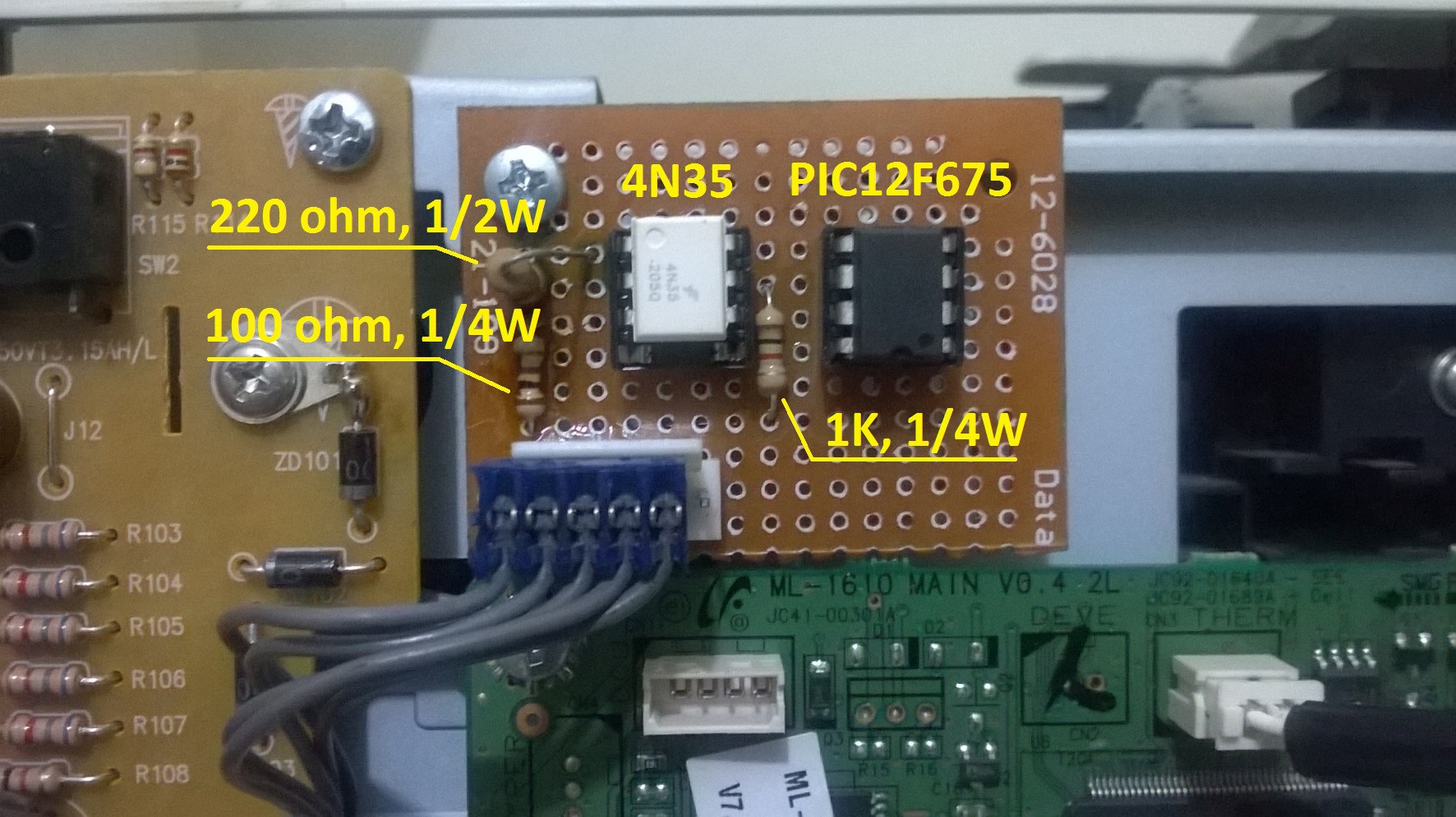
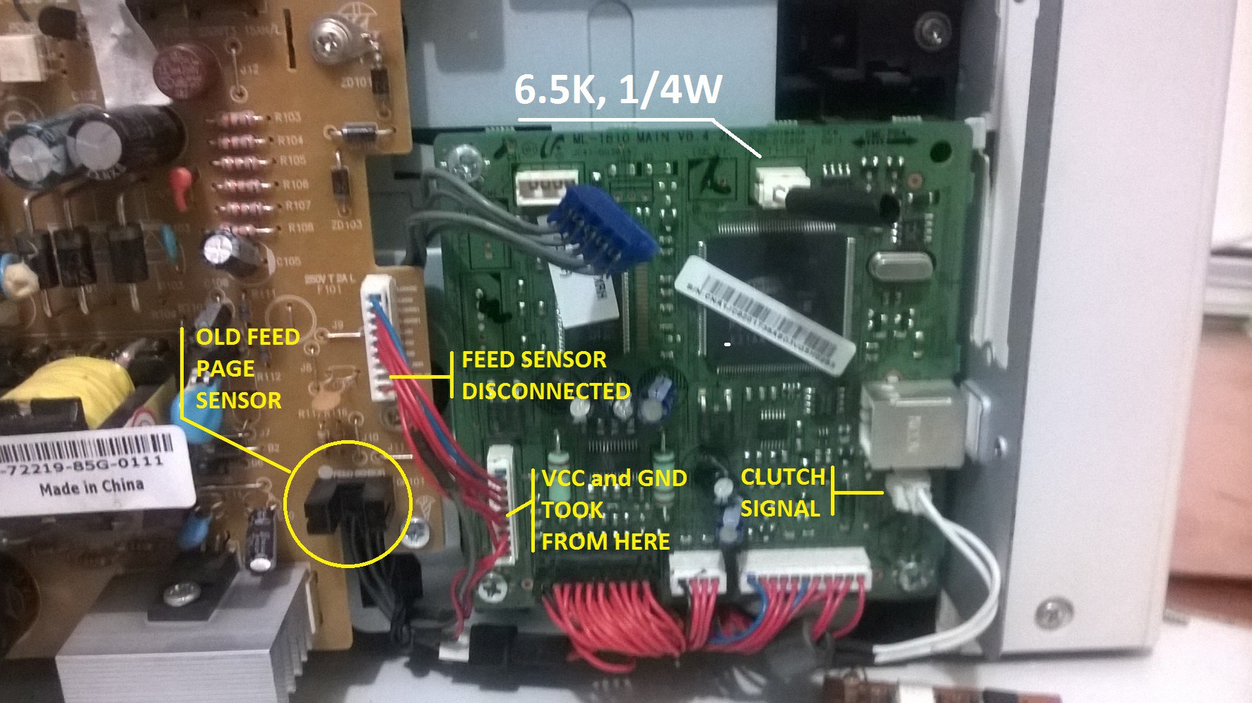
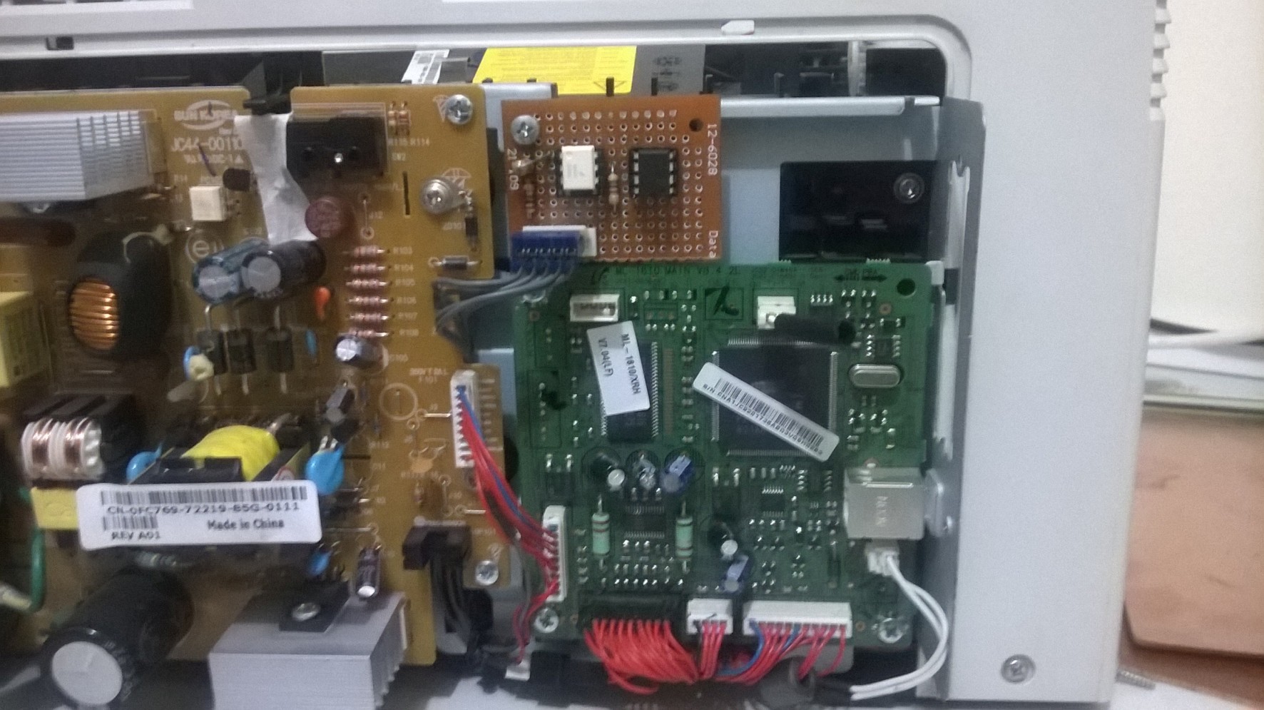
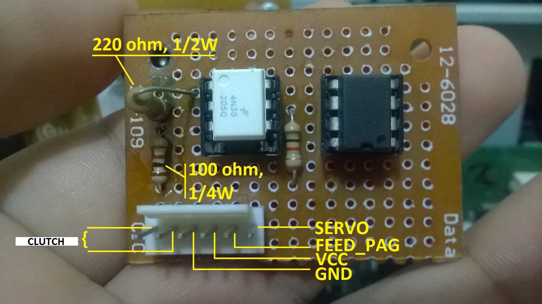
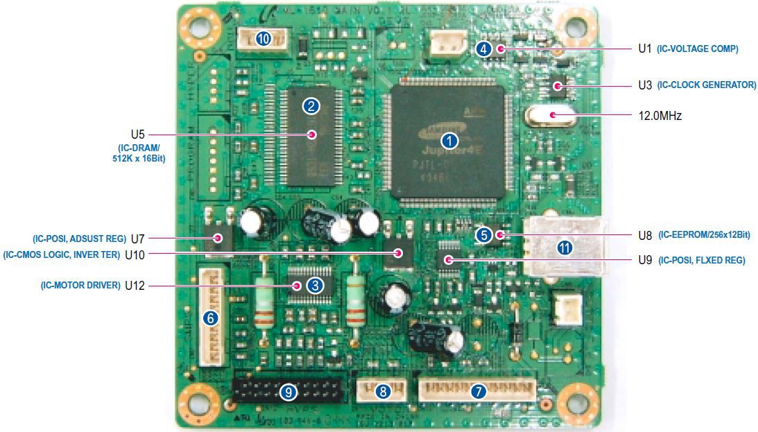
The printer detects the paper and follow up the whole printing process using simple IR sensors that provide digital information to the main board, so in order to keep the original control system we should find the way to provide the same information that the IR sensors, we are talking about the timing in the signals that IR sensors provide.
The Service Manual of the Xerox Phaser 3117 provides a System Timing Chart for A4 format, but I strongly recommend get the timing from the real circuit helped by an oscilloscope.
The "blinding" process also include the Fusor stage deletion, from this stage we have a Thermistor sensor that is easy emulate with a 6.5k - 1/4W resistor, please refer to the schematics of this article for more information (Fusor deletion)
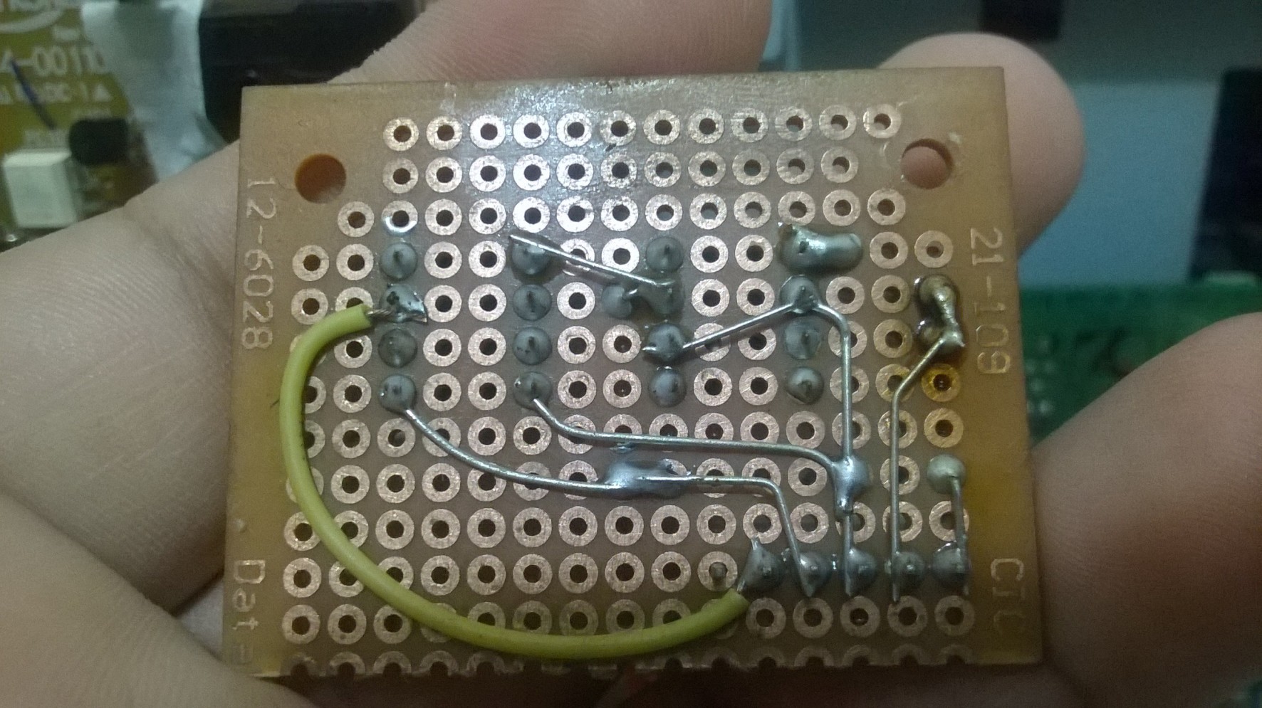
II - Mechanical adaptation
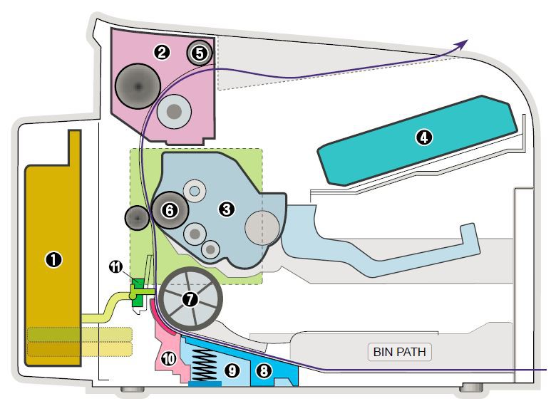
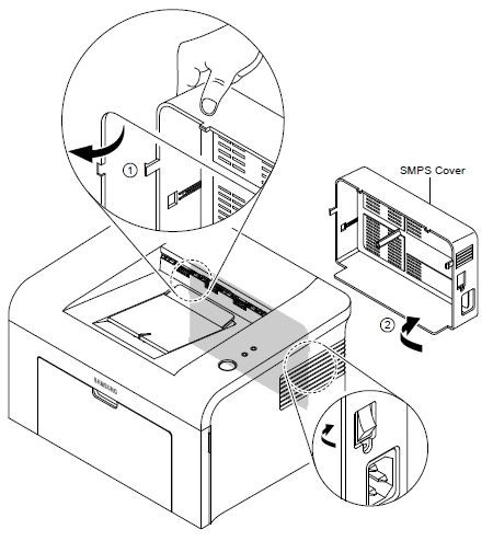
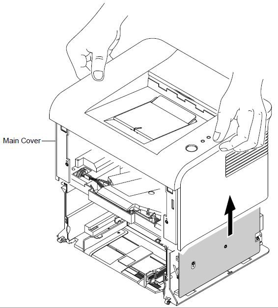
After make the printer blind, we can start with the mechanical adaptation. Since we have that the paper is following a "C" route we should adapt the printer in order to open a straight way to allow the PCB go through the printer.
III - Quality improvement
Now that we have the printer making the basic task (put toner on the PCB) we should focus on improve the quality of the toner layer to avoid holes and white lines. If we are working with an old printer is it possible we should replace the cartridge and continue with our lives, but in case you found very difficult get a new cartridge (because this model is recalling), an option is repair the old one (my case).
(it will continue ... )
IV - Input automation
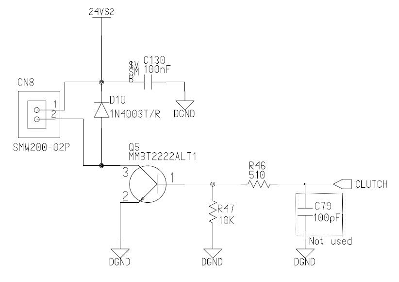
The printer process starts with the "clutch" signal. In the original system this clutch signal powered a Solenoid in order to feed the paper into the printer. This time we are using this clutch signal in order to have a reference, a start point, to generate the emulated IR signals, so why not use the same reference to activate a servo in order to feed the printer with the PCB.
In the follow image you can see the circuit that generates the clunch signal.
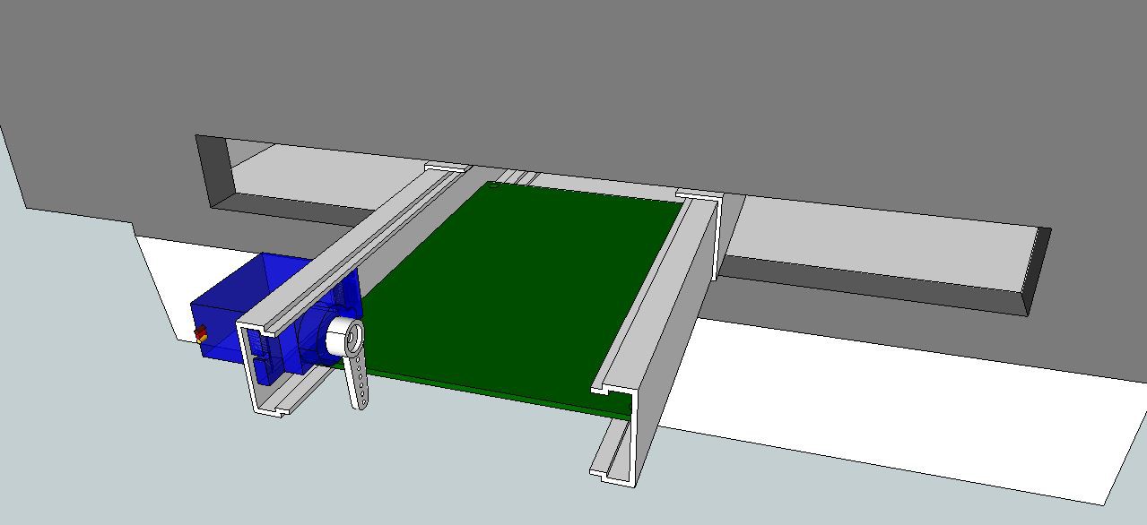
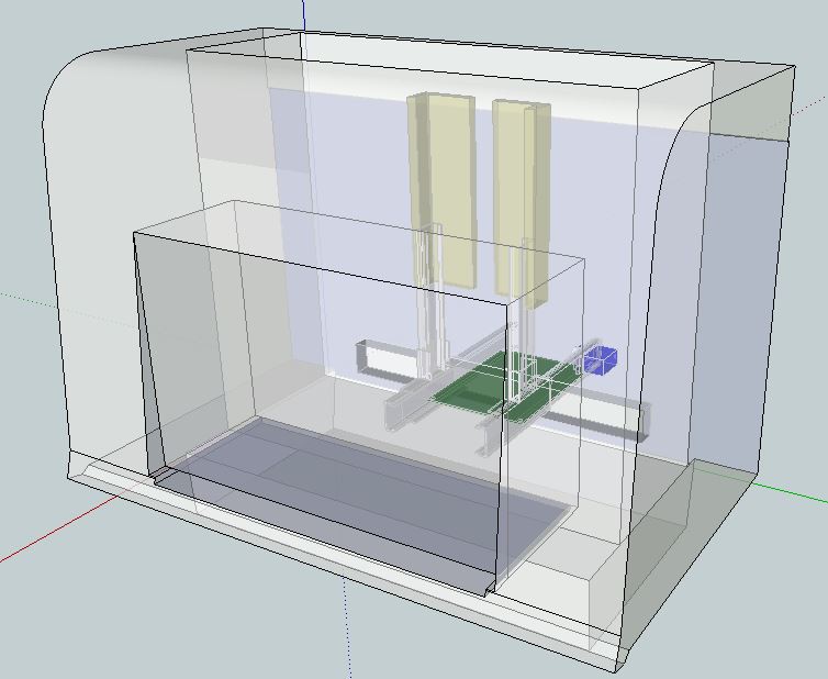
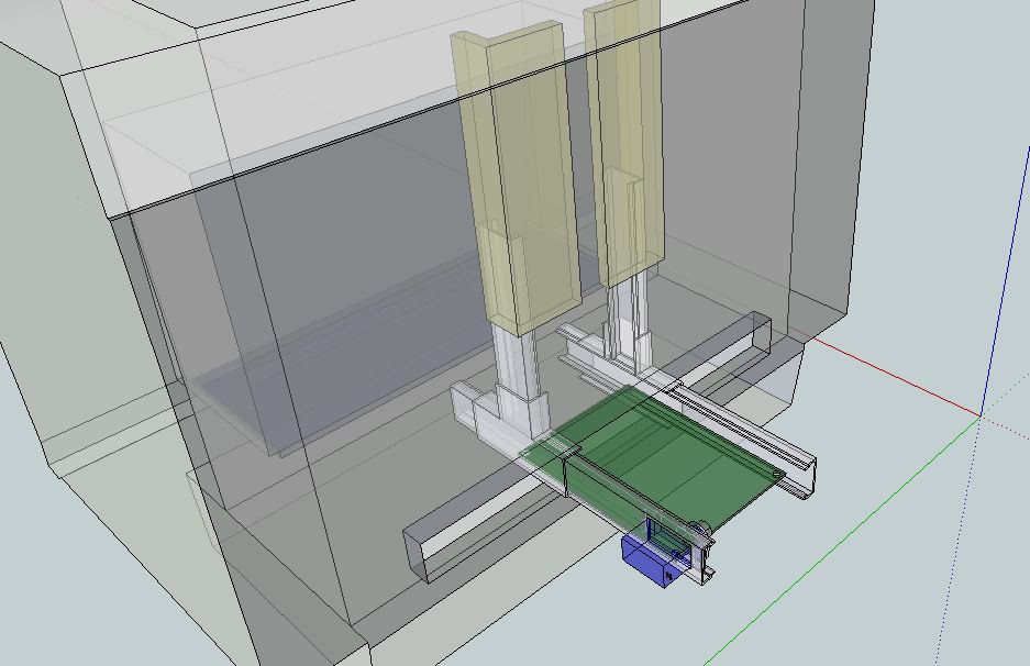
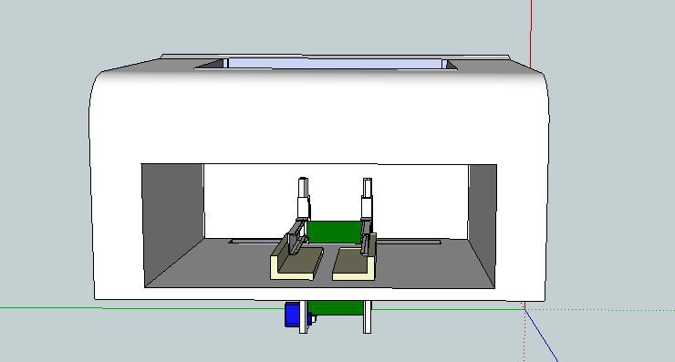
The basic idea to adapt the printer to feed PCBs to the printer is the follow:
The follow image shows the position of the mechanical adaption and its location into the printer.
As I mentioned at the beginning of this article, we are trying to take advantage of the mechanical solutions already present in the printer, so on this time we are using the entrance paper guides in order to fix the new input platform.
 advancer01

 mayukhnath
 Pavel Semenov
 Martijn Schouten
 BotFactory
where are the valid links to download?
you could fix the download links?