0%
0%
LIR2450 USB Charger
Charge LIR2450 coin cells over USB
 Chris
ChrisBecome a Hackaday.io member
Already have an account? Log in.
Just one more thing
To make the experience fit your profile, pick a username and tell us what interests you.
Pick an awesome username
hackaday.io/
Your profile's URL: hackaday.io/username. Max 25 alphanumeric characters.
Pick a few interests
Projects that share your interests
People that share your interests


 Jasper Sikken
 jasonwinfieldnz
 Patrick Van Oosterwijck
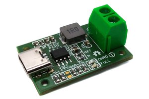
 Stefan Wagner
Forgot to update it here: The circuit is charging the coin cell but the led indicator does not work. I am not sure if it's because I got a cheap chip from Aliexpress or what else ... The circuit is almost the exact copy of the reference implementation from the data sheet. The charging LED is on all the time and does not turn off. However the chip is charging correctly. Once the cell is full the amperage going to the cell is almost zero.