 Shree Kumar
For the past couple of years, me & my team have spent a lot of time working with & refining Kiteboard & Kite. Things kind of evolved to reach the current state. Looking back, I can’t find a single document that anybody wrote which summarizes the design in a useful manner. This post is an attempt to explain what has happened till now, and how we intend to change things in the future.
Before we go into design, architecture, etc, I would like to offer a simplified bird’s eye view of what goes into creating a phone. I am painfully aware that it’s a simplification of a rather complex process fit into a few short paragraphs. If you are an expert, please excuse any inaccuracies in the next few paragraphs 😊
Smartphones are based on SoCs – basically a lot packed into a single chip. SoC vendors (Qualcomm, MediaTek) don’t stop at providing just SoCs, they provide complete reference designs for phones. Generally, a reference design tightly integrates various chips from the same vendor – the SoC, a PMIC (power management IC), WiFi/BT, RF circuitry, and Battery Charging. Reference designs also include other parts required to build the full phone: RAM, storage, peripherals, connectors, antenna designs, and everything including the enclosure of the phone. A reference design generally provides several alternatives for various components (it’s a huge market, choice rules!). Reference designs represent reasonably tuned solutions, from a hardware, software, cost and performance perspective (that is saying quite a lot in one sentence, by the way!).
Most smartphone vendors leverage the reference designs, changing mostly the “peripherals” – display/touch, cameras, maybe sensors, casing, battery. Peripherals & the base platform decide the market positioning of the device. Making a smartphone is a tight exercise in space optimization too. For every device, shape of the board and connectors on it are changed to accommodate the selected peripherals & the overall design. Antennas are designed & positioned carefully, and are highly influenced by safety testing (SAR) considerations.
Overall, a complete smartphone is a single block of tested hardware & software. It is “hard”ware – hardcoded (in software terms) to achieve a single, cost optimized device. Mass market consumer devices essentially go through an aggressive BOM optimization, which eliminates unnecessary components – down to the lowly resistors. Smartphones are designed to sell in the millions. Even a few wasted resistors are a no-no at that scale.
Reference designs are the secret to the flood of devices you have been seeing in the market for the past N years. Most devices based on any given platform don’t differ much in terms of performance and feature set.
Abstract Design of Kite v1
We wanted to create a design that would allow us to build a variety of devices using a standard set of components. Here’s a block diagram that reasonably captures the design of Kite, in generic terms – without reference to specific technology:
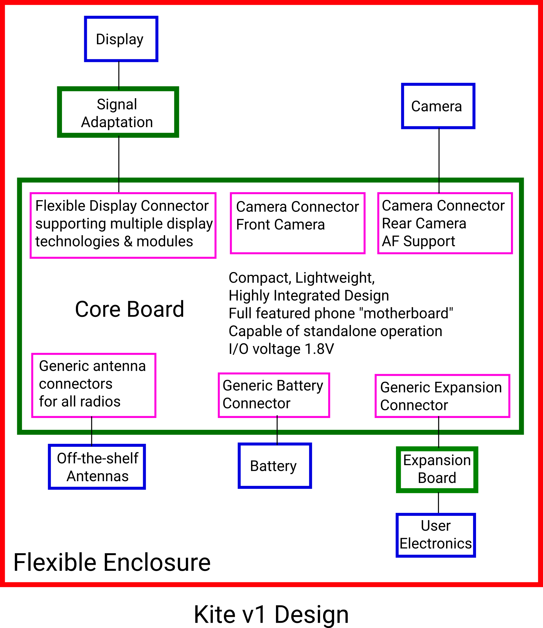
Before I get down to explaining each piece, here is the color coding used in the block diagrams in this post:
- Green for PCB
- Blue for peripherals
- Pink for connectors
At the center of the design is a “Core Board” (henceforth shortened to “Core”). It’s basically the guts of a full featured smartphone… If I were to draw an analogy with the PC, I would call it the “motherboard” of a smartphone. Basically, this includes the important, tightly integrated parts of the reference design. It skips most of the peripherals, opting to route necessary signals to connectors.
The connectors on the Core are kept reasonably generic. This gives us the flexibility to change the peripherals, without changing the Core.
The expansion connector on the Core includes important signals that allow us to create custom devices of various form factors. All the signals a user needs to add their own electronics must come here.
User electronics may operate at a different voltage level (3.3/5V) compared to the core. An expansion board can take care of the signal level conversion.
The battery connector on the Core must support everything required to connect & monitor the status of any battery.
The display connector on the Core needs to be generic enough to support multiple display technologies:
- Mobile displays with integrated touch panels
- HDMI monitors with audio output
- Other panels like LVDS and RGB
Since the display connector is generic, it cannot connect directly to any display in the world ! The required signal conversions can be done by a display specific display board.
Similarly, we need camera connectors. However, we can afford to be a little less generic (and specialized) in the case of cameras, as they are specialized devices (compared to displays, at any rate).
A phone includes various type of RF antenna: a primary RF antenna, a diversity RF antenna, a WiFi/BT antenna and a GPS antenna. The signal lines for these can be routed to a generic connector, once for each antenna.
Once generic antenna connectors are available, commonly available off-the-shelf antennas can be attached to them.
Finally, all this can be enclosed in a flexible enclosure, that allows customization by users.
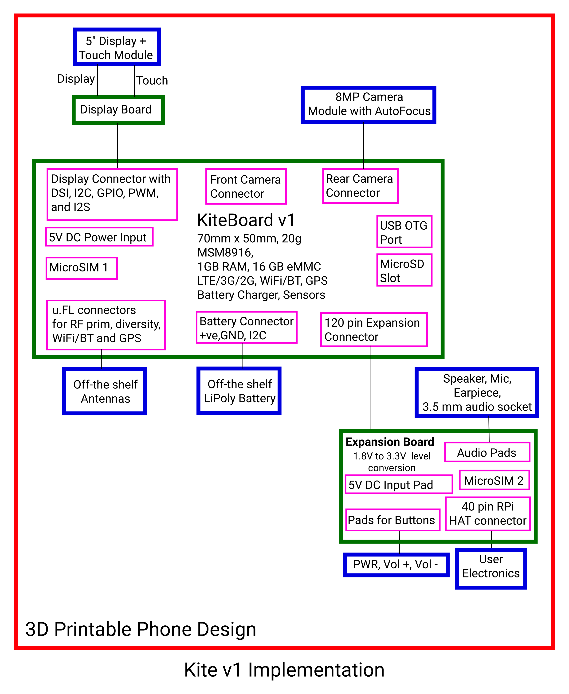
Implementation of Kite v1
Abstract designs are great – they help us think in generic terms. When a design is converted to an actual physical implementation, important decisions (and naturally, trade-offs) need to be made.
Before I explain the actual implementation, I need to explain the general philosophy around the implementation.
Early on, I realized that a DIY phone making kit must have the following desirable properties:
- Must be a flexible kit.
- Must be based on off-the-shelf components to the maximum possible extent.
- Must rely on consumer grade 3D printing (FDM) for making a case around the components.
- Must allow user to add their own electronics. After much thinking, I mapped this to a requirement of implementing a 40 Raspberry Pi HAT compatible connector.
- End device must be compact enough to be called a “phone”. However, size reduction must not trump accessibility for the hacker.
- Simple design, easy to assemble.
Now, let’s see how we mapped the design to the implementation of Kite v1, with the philosophy in mind:
And here is Kite itself:
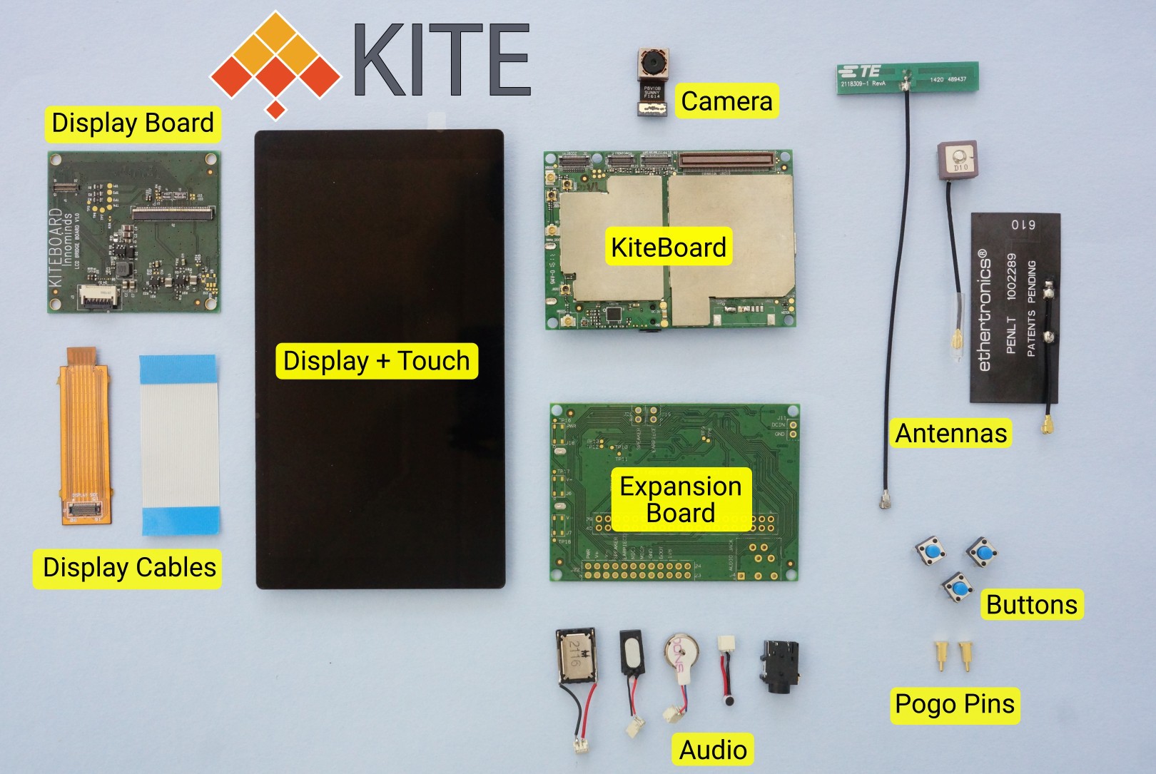
The picture above will look familiar to those who have read the log post about Poorna, the minimal phone built with Kite. Note that the design files (3D models, schematics) are available.
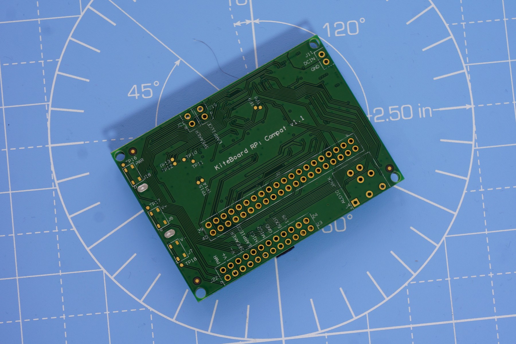
KiteBoard v1
The Core of the design is implemented in the KiteBoard. First things first – KiteBoard was not created exclusively only to make a smartphone (i.e. “Kite”). During the course of many years, we had seen that customers more or less wanted the same device with some differences. KiteBoard was an attempt to create a common platform that could meet diverse needs.
Individual makers & professional device makers (i.e. companies – my normal customers) have some requirements that are divergent. Professionals want to create something cost optimized; they generally don’t mind complex designs. Individual makers/startups need access to complex designs in a way that they can use. Commercially available boards that target makers generally have large connectors, 0.1” spaced pads, among other things. Several companies make available “SOM” modules that target the pros – these are generally hard to use standalone. Where do we draw the line?
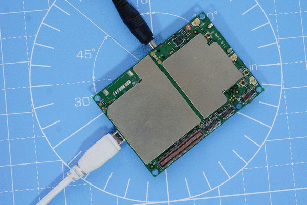
After much deliberation, we settled on a hybrid SBC/SOM approach to create KiteBoard v1. KiteBoard was implemented with MSM8916, a successful global platform not just for smartphones – but also for us. KiteBoard includes the “core” of a phone – integrating 1GB RAM (+16 GB storage), LTE/3G/2G, GPS, WiFi/BT (+FM radio too!), and battery charging with a dedicated DC option. Plus 9 axis accelerometer, ecompass, gyroscope.
KiteBoard is designed to be standalone. So, we added a microSD slot, and a micro SIM slot. The selling pitch was, “power it on, and it will boot to Android & connect to the internet”. We implemented the required connectors on KiteBoard. KiteBoard has a RGB led on it, here’s the mandatory LED blink in action - with a slight twist: we have a tiny RGB LED on board - so we do an RGB dance. DC jack & USB are both connected. In the animation, below the red led looks a little weak - it's not so in real life...:
The following commands were used to do the animation, in the adb shell (note: no PWM and brightness control here)
$ cd /sys/class/leds
$ echo 1 > red/brightness
$ sleep 1
$ echo 0 > red/brightness
$ echo 1 > green/brightness
$ sleep 1
$ echo 0 > green/brightness
$ echo 1 > blue/brightness
$ sleep 1
$ echo 1 > red/brightness
$ echo 1 > green/brightness
$ sleep 1
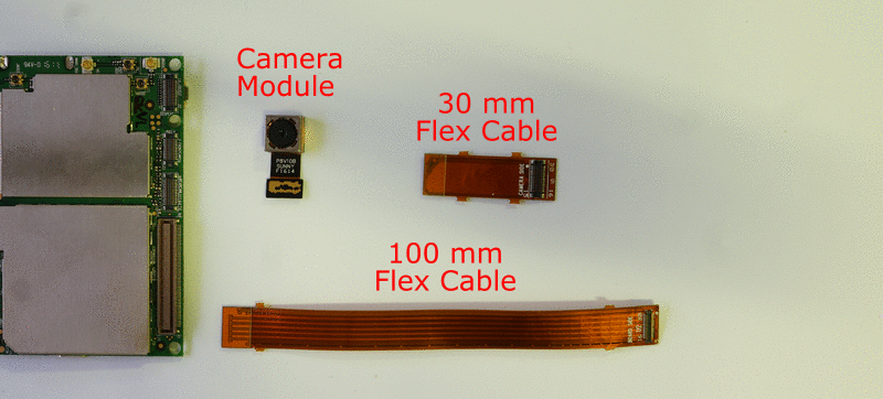
The camera connectors implemented essentially a direct plugin option for two specific camera modules we were already using. This was deemed sufficient at the time. We used an existing 8 MP camera module with autofocus support as the rear camera. The connector on the board matches the camera. The camera can plug in directly onto the board – this helps to minimize the form factor while building a phone. Sometimes, there will be a need to place the camera a further distance away from the board. For that purpose, we have flex cables of two lengths: 3 cm and 10 cm. These cables are designed so that they may be combined to achieve a longer length, if required:
The display connector was designed to be highly generic. Mobile displays are generally based on MIPI DSI, generally the only native display option on cost optimized mobile SoCs (such as the MSM8916). We routed all the MIPI DSI lines to the touch connector. The touch panel on a mobile phone is typically based on I2C, that’s two more lines. Backlight control needs a PWM signal. For audio output, we needed I2S. Finally, we added power lines and a few spare GPIOs to complete the display connector. With this design, we were sure that we could do a lot. (Our 5" phone display and HDMI display have proved that already)
In the case of antennas, the choice of connectors was straightforward – we just chose u.Fl connectors. The range of antennas supporting that connector is huge. You can also buy “pigtails” that allow connection to larger antennas that have an SMA connector.
For the WiFi/BT, and LTE antenna we chose parts from DigiKey. We made an exception for the GPS antenna – we took a few samples of DP-10 from Sanav, which they claimed at that time to be “the smallest GPS antenna in the world”.
The biggest point of discussion was the expansion connector. My initial idea was that this would include only the low speed signals (free GPIO, UART, SPI, I2C), audio signals, and the second SIM. However, given that the Kiteboard was supposed to be used for other products, it ended up becoming the kitchen sink of all signals. A large number of additional signals were routed to it – USB, SD card, DC power, system power, …. The expansion port ended up being a 120 pin dense connector.
Expansion Board
The expansion board (in its current state) was made much later than the board – it was more or less designed together with the phone enclosure. The expansion board was engineered to include a 40 pin Raspberry Pi compatible HAT connector footprint. The expansion board stacks right on top of KiteBoard. There are no components on the top side, everything is at the bottom. This helps reduce "thickness". The stacking height of the 120 pin connector is 4mm.
The Pi works at 3.3V, while the KiteBoard is at 1.8V. That requires a level converter in between. The level converter allows us to select the select the “output side” voltage level. For compatibility with the Pi, we set this by default to 3.3V. However, we do have resistor options to set this to 5V, if required (very useful to make the expansion board compatible with 5V electronics used with Arduino). The level converters also implement useful ESD protection.
The expansion board also implements pads (0.1 inch spacing) for audio signals – speaker, mic, earpiece. Standard buttons (power, volume up & volume down) are also exposed on 0.1 inch spaced pads. We also threw in a footprint of an audio jack to complete the expansion board. We routed the earpiece & speaker signals to two places, to make it easier to connect these components.
To provide sufficient power at the 3.3V and 5V connectors, we included power regulators that generate the required levels & output from the system power. The enable pin for these regulators is set by the KiteBoard on boot. However, it is also possible to set these high. If this is done, then we can have the external electronics powered on always. This feature could be used to implement some very interesting things. I intend to cover this aspect in a future post – it’s an unexplored novelty of sorts!
We used off the shelf components for speaker, mic, earpiece. All these can be purchased in a single quantity from Digikey; that’s where we purchased them. The vibrator was sourced locally from hacktronics, a local online retailer for hobby electronics.
In the battery connector, we included an I2C bus. This could have come in handy, if we ended up using a battery pack which includes a fuel gauge. We already had such battery packs in other products, and it made sense to have this option.
We did not want to spend money customizing a battery, so we chose to use off-the-shelf LiPoly batteries.
To complete the kit, we sourced a nice 5” display module with an integrated touch panel. We made an intermediate display board that adapted the display connector to this display module. The display board connects to the KiteBoard using a flex cable. This flex cable can be connected end-to-end to place the display farther away if needed.
Lastly, we got a talented graduate intern to design the case…. That’s the same design that you see in the pictures & videos. To ensure that the audio components can stay in place, we sourced small connectors locally. That’s how, we ended up with Poorna, our minimal phone design.
Learning from Kite v1
We’ve now been playing with this design for more than eight months. We’ve built a lot of prototypes with it & learnt a lot. Every prototype is essentially a mini project (that takes less than a week to make, BTW)!
I have used Kite as a primary phone for over one and a half months. I found that it worked well – I could use it for a whole day, with a usage pattern that’s not centered on media consumption. That didn’t turn out a surprise to me, as I understand the power characteristics of the underlying platform quite well.
I have also noticed that the WiFi signal reception on my KitePhone is superior in many places, even when compared to a flagship phone that I use on a daily basis. The race to make everything thin certainly hasn’t come at the cost of great wireless performance in all situations… That said, it would be wise of me not to make tall claims without a thorough analysis of this! I intend to publish some results after I do a better comparison.
My primary complaint has been the RAM on the device (1GB). Switching away from Facebook to Facebook Lite solved most of these problems. However, Android does work much better with 2GB RAM than 1 GB RAM, even on Android L. Of course, we could all do with a nicer processor, among other things – which is what Kite v2 is all about!
The real revelation to me, though, has been the hardware modification aspects. When I now look back, I see that I have exceeded even my wildest expectations. Many of these builds are being documented as logs on these pages.
The intent of this post, though, is to point out the flaws. What went wrong. Here's my laundry list of what I think needs improvement:
- The expansion board is way more complex than what it should be. An ideal expansion board must be ultra-low cost, and easy to fabricate, ideally with a low-cost process (trace width 8 mil, clearance 8 mil?)
- It is would be nice if custom electronics could be swapped in & out in an easier way
- A soldering free design is a must for the base phone. This has been a common request from a lot of folks who have seen the design. I strongly agree with them!
- To achieve (1), need to simplify the expansion connector by drastically cutting down on the unnecessary signals. Somewhere in the range of 40 pins is ideal. Pin count on this connector must certainly not exceed 60.
- At-least a few pins on the expansion connector must be able to drive sufficient current for glowing an LED at a decent intensity…
- The expansion connector must not “stack” onto the KiteBoard. Preferably, it must lie in the same plane… This will help reducing the “thickness” of the phone.
- The LTE antenna needs a dedicated place. Preferably close to the speaker.
- The next version of the flex cables must not have “L” cuts. That tends to promote tearing at the junction.
- We need a good battery connector & a custom battery (in the kit). These are required for a good experience (including “soldering free base kit”) for everyone.
- The 3D design needs improvement. Not everything is as nice as it should be. To make it very easy to modify, we need it to be available as a nice parametric “solid” modifiable in FreeCAD.
How do I propose to fix these? I have most, but not all the answers. Here are some good ideas:
- Keep audio signals & buttons on the main board. Add connectors for these signals. That will take care of making this a soldering free design. For users who want to use the expansion board, it will simplify the experience of changing the hardware
- Move the 3.3V & 5V power regulator to the main board. With this additional change, the expansion board will be reduced to a “level converter only” board!
Right now, though, I don’t see a reason to spin the hardware to make these changes. We intend to do those for Kite v2 – our crowdfunded design. More details about Kite v2 are in this log entry.
Discussions
Become a Hackaday.io Member
Create an account to leave a comment. Already have an account? Log In.
Great!, any info regarding campaign launch date?
Are you sure? yes | no
Very close @SathyanKrishnan ! I see you have subscribed for updates. Thanks for that. Will let you know.
Are you sure? yes | no
@SathyanKrishnan see launch date & some change in plans https://hackaday.io/project/42944/log/144229-important-an-update-crowdfunding-d-date-23-april-and-a-downgrade !
Are you sure? yes | no