 ccates
I started by looking up the data sheets on the two chips found on the board - the ST2226A and the 74HC245.
The 74HC245 is a standard high speed bidirectional 8 bit buffer. Datasheet is here: http://pdf1.alldatasheet.com/datasheet-pdf/view/351465/ONSEMI/74HC245.html
The ST2226A is a PWM constant current LED driver designed for displays. Datasheet is here: http://pdf1.alldatasheet.com/datasheet-pdf/view/192941/ETC2/ST2226A.html.
First I did some basic snooping with a multimeter in continuity mode. As expected, all of the ground pins on the chips go to the ground on the power connector. I also verified that the ground for the VccR power supply side of the power connector is the same as the ground on the VccGB side. Ground is ground the world around. Next moving to the VCC pin on the chips I found that all chips got their power from the VccGB power input.
At this point I knew from the datasheets that all the chips could run safely on 5 Volts. I thought "What the heck - let's see what happens" and proceeded to connect my 5V breadboard supply to the VccGB input. Upon flipping the power switch I was rewarded with a pretty pattern of random of glowing green and blue LEDs. Yaaaaa!
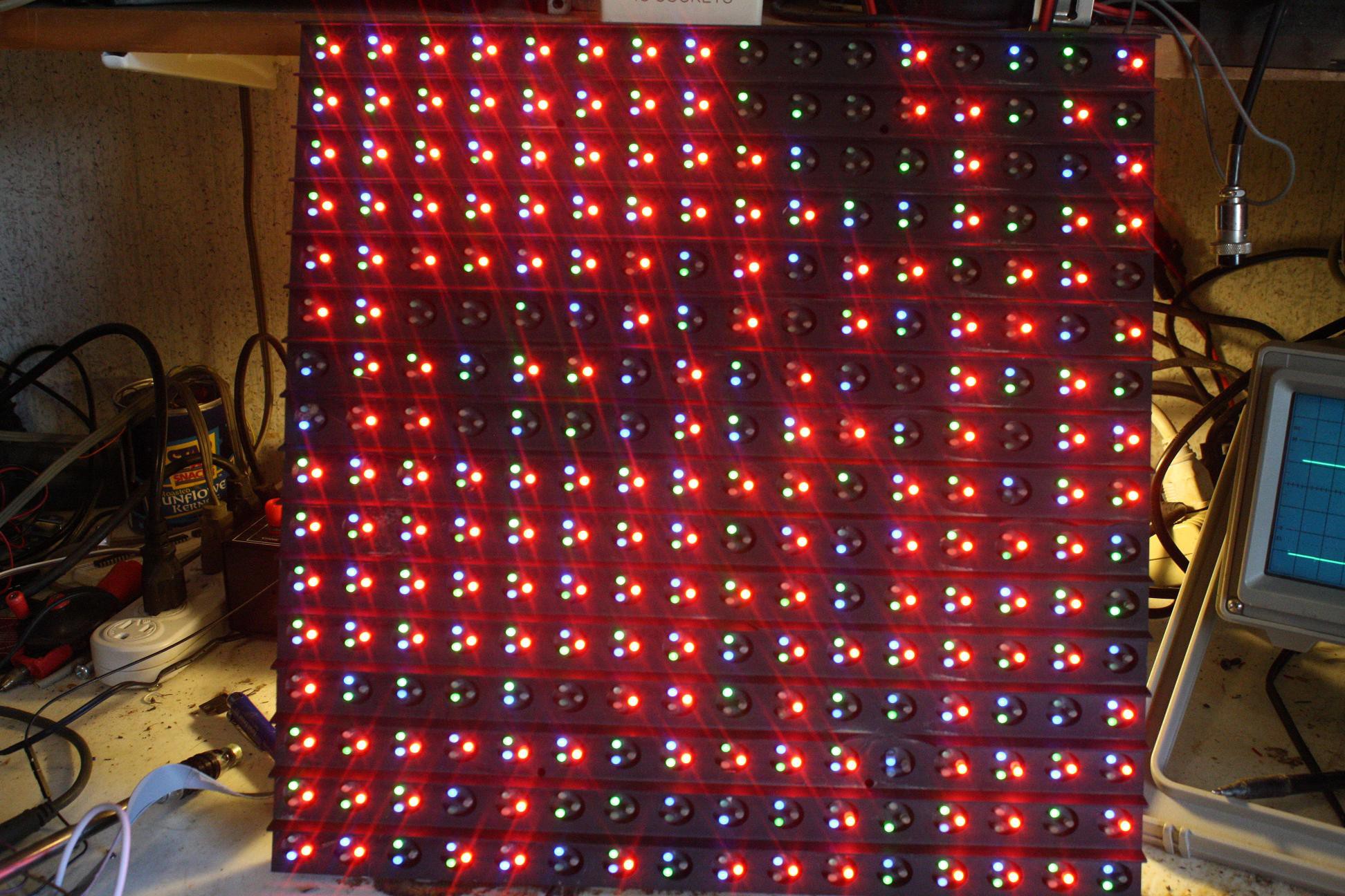
Strangely enough flipping the switch off then on repeatedly produced the same pattern. I realized that the large cap on the power supply was keeping the pattern in the chips. Turning off the power supply and shorting the cap allowed me to get a new random pattern each time. Fun but it was now time to get serious.
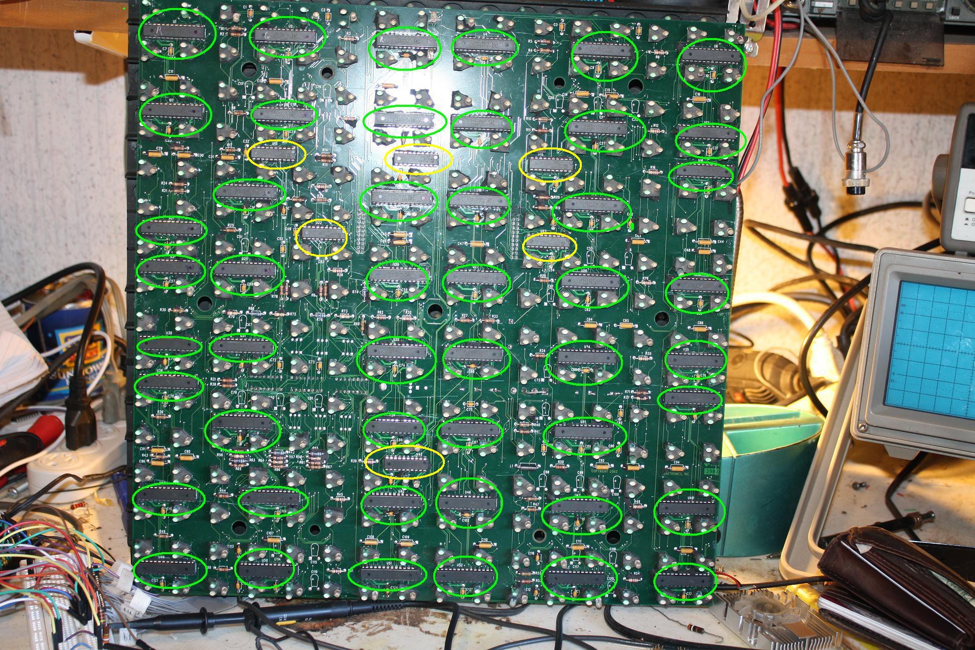
The driver chips on the board were arranged in a six (x) by eight (y) matrix. (Drivers circled in green, Buffers circled in yellow)
Beeping through the top left driver chip using the continuity test I found that that chip serviced the red LEDs in the 8 pixels above and below the chip. The next driver chip to the right serviced the green LEDs in the same pixels. The next driver over took care of the blue LEDs.
The top row of 6 Drivers serviced the 16 pixels above the chips and the 16 below for a total of 32 pixels being served by each row of 6 chips. This pattern follows for each of the 8 rows of 6 chips down the board. 32 pixels per row * 8 rows = 256 pixels. 3 colors per pixel gives us 768 LEDs.
Next: The buffers and the input connector
Discussions
Become a Hackaday.io Member
Create an account to leave a comment. Already have an account? Log In.