 ccates
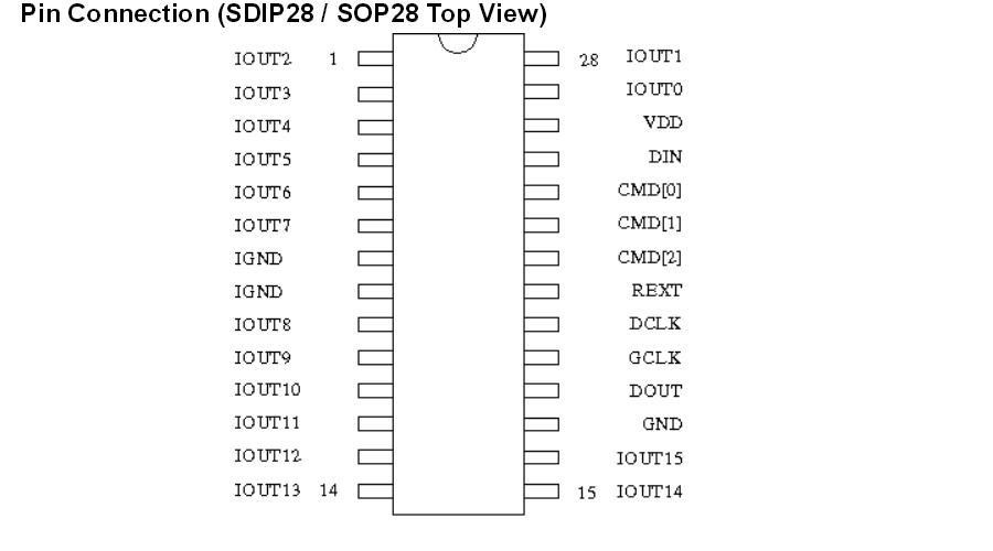
The DataIN or DIN signal is the pathway that gets the data that needs to be displayed into the panel's driver chips and thus to the LEDs. It is a serial input signal and each driver chip in the design takes 160 bits in to drive it's 16 LEDs at 10 bits of luminance per LED. The driver chips are daisy chained - Each one has a Dout pin that can be tied to the next chip in the chain. If all of the drivers were chained end to end this way the entire chain of 48 chips would require 7680 bits to be clocked in per frame. While it is possible to do this it seems the engineers at Daktronics wanted to be able to get data in a little quicker so they separated the DIN signals in two ways - they separated the panel into a top and bottom half and separated each color (Red, Green and Blue) from each other.
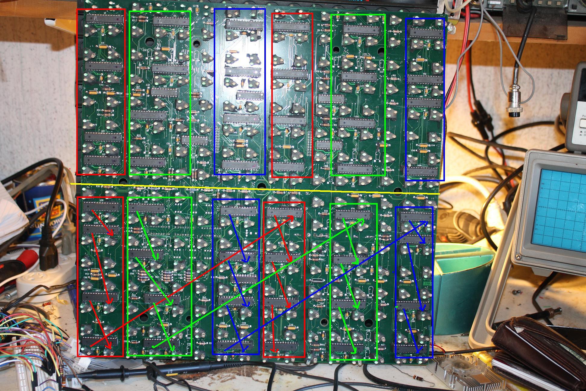
Again much beeping of my meter led me to discover that there are 6 separate DIN signals: TopRedDin, TopGrnDin, TopBluDin, BotRedDin, BotGrnDin and finally BotBluDin. The panel data inputs are thus separated into a top and bottom section of 8 driver chips for each color a total of six separate sections with 6 separate inputs. Both top and bottom sections are identical in signal path - The din signal starts at the top left chip through then down to the next chip in the column and then to the other quadrant asshown on the bottom section. Tracing these signals to the Input connector leads through a buffer for each section in U13 (top DINs) and U15 (bottom DINs). On the input connector the inputs are as follows:
TopDinRed - Pin 19TopDinGrn - Pin 6
TopDinBlu - Pin 15
BotDinRed - Pin 11
BotDinGrb - Pin 12
BotDinBlu - Pin 13
This input arrangement makes the data speed requirements much easier to accomplish. Rather than requiring 7680 DCLK cycles to clock the bits in serially in order to refresh the whole panel, you can send all six DINs in parallel and make it possible to input a frame in 1280 DCLK cycles. This means a ten frame per second rate only requires 12,800 DCLKs /second and a full video rate of 60 frames per cycle requires only 76,800/second. While full video is probably still out of the range of an Arduino it should still be possible to get a decent animation rate
Next: Wrapping up the hardware - Dout, Rext and the output connector
Discussions
Become a Hackaday.io Member
Create an account to leave a comment. Already have an account? Log In.