 Chris Hamilton
The 12axis Flex Module contains an LSM9DS1TR and BME280. The LSM9DS1TR is an accelerometer, gyroscope, and magnetometer or as commonly referred to as a 9-axis sensor. The BME280 provides barometric pressure, humidity, and temperature sensing. So I am calling it a 12axis Flex Module.
The board is configured for i2c communication. LSM9DS1TR has a separate address for the magnetometer from the accelerometer and gyro. The address least significant bit is selectable for those as well as the BME280. I have routed the first interrupt of the accelerometer/gyro as INTG and the magnetometer as INTM. The data enable pin of the accelerometer/gyro and the data ready pin of the magnetometer are also exposed.
Defaults addresses for the LSM9DS1 are as in datasheet and not common to most drivers based on the LSM9DS0. So adjust any examples from Adafruit, Sparkfun, etc. accordingly.
LSM9DS1:
- Accelerometer/Gyro 0x6A (0x6B A.G solder bridge shorted)
- Magneto 0x1C (0x1D A.M solder bridge shorted)
BME280
- 0x76 (0x77 A.B solder bridge shorted)
Any software related will be released under BSD or MIT license. SAAS or cloud based software will be AGPL.


 Daren Schwenke
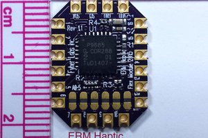
 uri.shani
 VASILIS VORRIAS
I love this project, so many applications. :) It fits the bill for a fun project I'm looking at for leveling machines.