 Kert
KertI managed to more or less finish the autodesk inventor assembly for the new revision last night. "More or less" because I did not bother adding the bolted connections everywhere where they should be. My inventor is on HDD and I suspect that which makes it to lag every time I add a new bolted connection. Rest of the PC specs I'm using for it should be decent enough to not choke on that (I7-3820 @ 4.3 GHz, 64 GB of RAM and AMD 7950 gfx card). But the point of the autodesk inventor assembly is anyway for me to see if there is any obvious problems I might have missed in the 2D design process. It does not happen often, but when you have forgot to move some opening 5 mm to the left on some component when you stretched another one 5mm in some direction it is better to find out that before I have the parts cut out and in the process of assembling it physically.
This time I used acrylic as the material for the sheet metal parts and one if the side effects of that is that the components are semi-transparent. I found out that this is actually a pretty nice for checking if any of the rods intersect or any of the linear bearings hit something they should not. Although I must add that doing the assembly is a bit more annoying with transparent components as it can be hard at time tell at a glance where are the borderlines even with borderlines highlight turned on.
What follows is a number of snapshots taken during the digital assembly process - in there it will be easier to understand what are the components and how are they arranged than a snapshots of the finished assembly rendering.
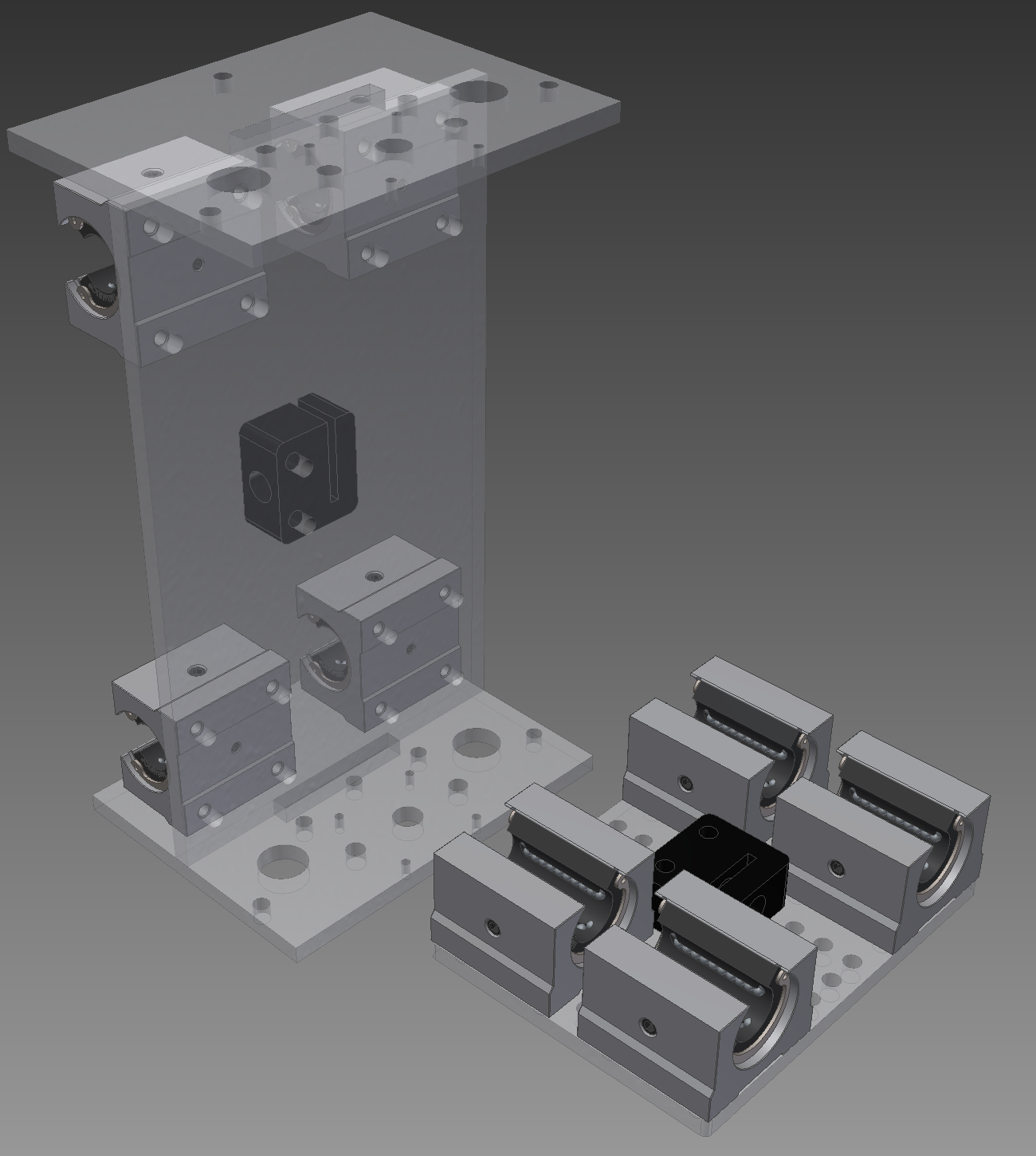
Fig. 1 - z-axis plate (right, horisontal) and the y-axis plate with linear bearings and delrin lead-nut (left, vertical). The horisontal plates on top and bottom of the y-axis are for holding the z-axis. I will probably glue them to the vertical plate although there will be also two 5mm threaded rods pulling the z-axis top and bottom plates together so glue might not be needed.
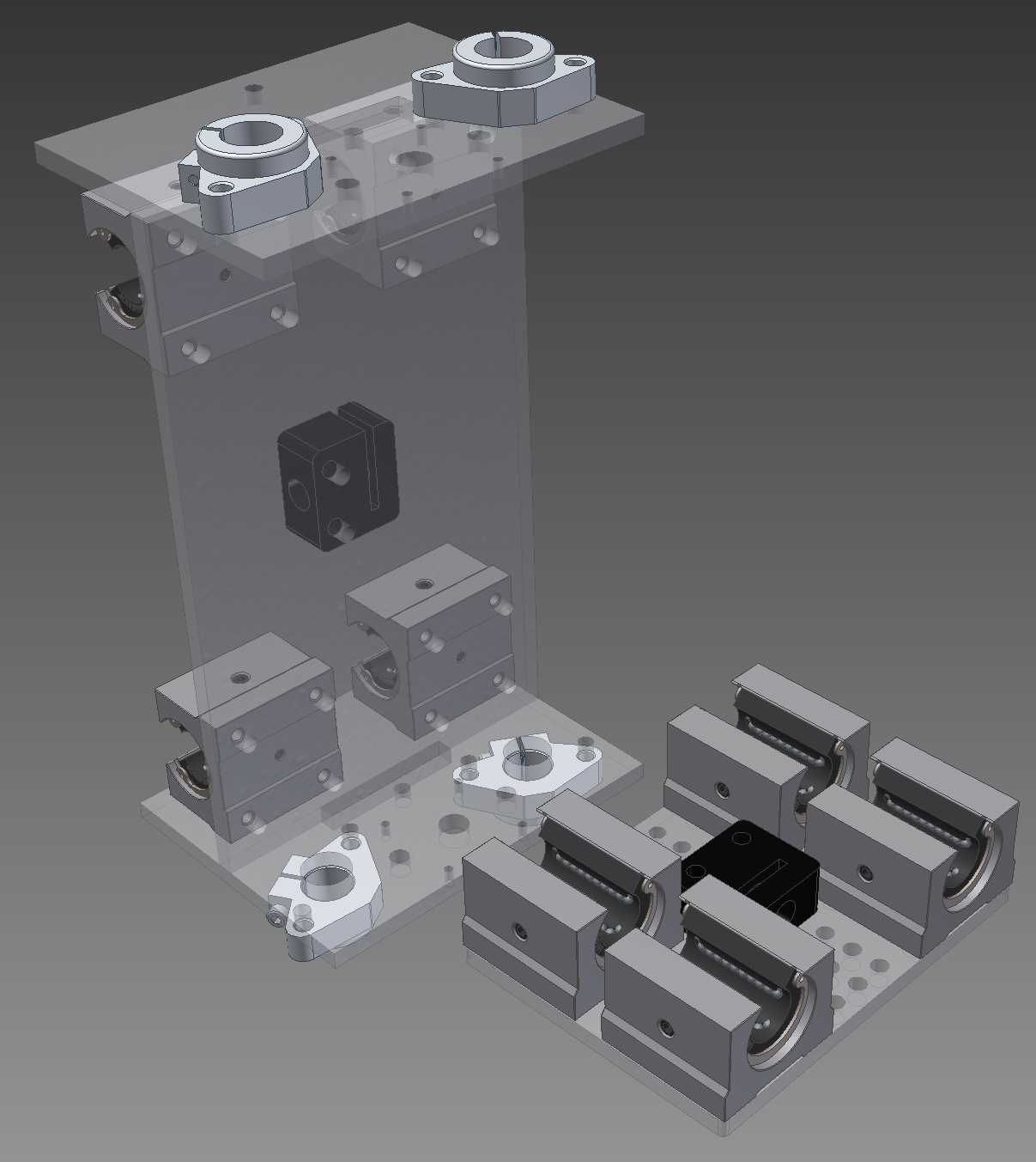
Fig. 2 - SHF16 blocks added for holding the 16mm calibrated rods in place.
It must be noted that some components I have grabbed from GrabCAD have issues - and I am not sure if I have misunderstood something myself or are some dimensions of these components wrong. For AutoCAD design process I did rough drafts of these components based on their dimensions in the spec sheets. However, NEMA17 engine and 10mm bearings have slightly different distance between mounting holes than specification for these components calls for. Same issue with the linear bearing blocks. Why is this issue - because when I am doing assembly and try to put constraints on these using the mounting holes central axis alignment for that I get an error message and must constrain them in some other way and this is annoying. It is possible that the guys who did these based their drawings on the actual physical components in their hands or it is also possible that I have missed something, somewhere. Regardless, when I look into my mounting hole I can see though the holes so reality will probably not care if the central axis of the mounting holes is displaced by 0.2 mm between components. I think ....
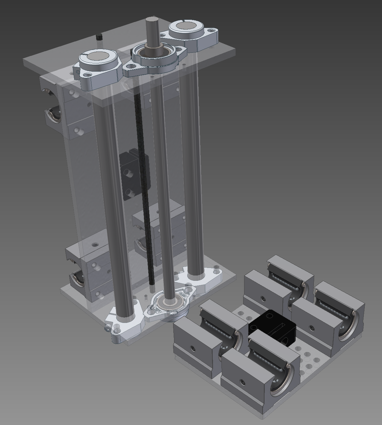
Fig. 3a - z-axis linear rods and leadscrew installed. Note the bottom section of y-axis plate, there seems to be a problem with SHF16 and the 10mm bearing block intersecting slightly.
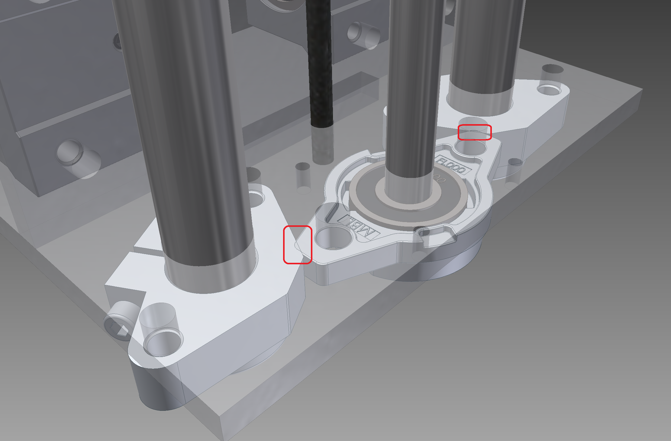
Fig. 3b - zoom in on the problem area. However, as I am not confident the dimensions of the downloaded components are entirely correct I will just ignore it for now as according to official spec sheet these component with max allowed dimensions within presented tolerances just barely should not intersect. If they do, in reality, then I will just have to grind a corner off from the 10mm bearing block to make it fit.
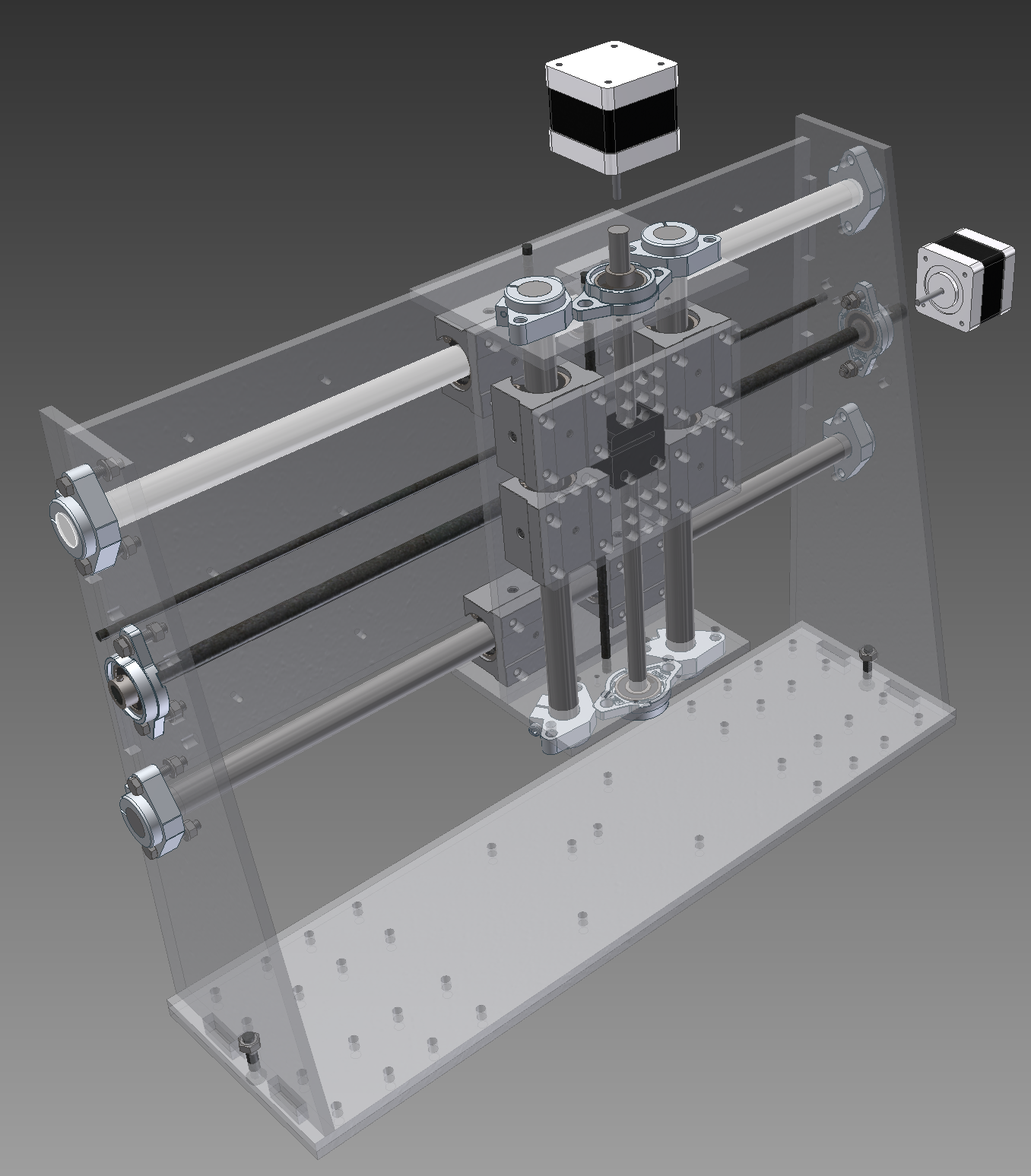
Fig. 4 - y-axis with z-axis attached to it. This is the stuff that shall be traveling along the x-axis. Note that as I decided to do the first version in acrylic and lost the little right angle corner pieces in this revision because of space constraints there is two 6mm plates in the bottom instead of the usual single plate. This is also only location in the machine where I used the "little tabs and bolthole" connection in the new revision because of the space constraints. I will most likely glue the bottom plates together although it might be also fine without glue because of relatively large number of bolts going though these two bottom plates.

Fig. 5 - Stuff to make base frame rigid. The underlying frame I plan to glue though quite thoroughly although there will be also a lot of threaded rod to stiffen it all up. This is the stuff going into there before putting constraints on them as that way it is easier to see at a glance what will be going into there.
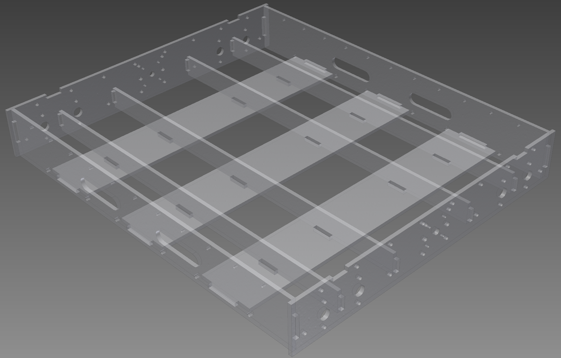
Fig. 6 - Base frame assembled view.
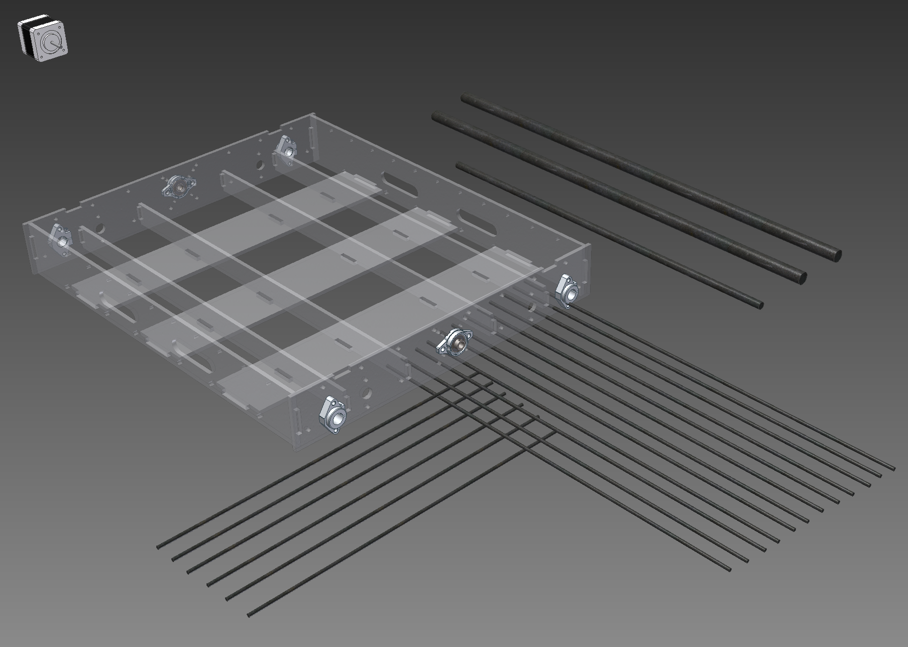
Fig. 7 - All the threaded rods going into x-axis and base frame. 2x 16mm linear rods (up to 4 of these can be used) 632 mm, 12x 5mm rod with length of ~615 mm (608 mm minimum) and a 10mm lead-screw about 650 mm long. In addition perpendicular tot he x-axis there is 6x 5mm threaded rods with the length of ~530mm (526 mm minimum).
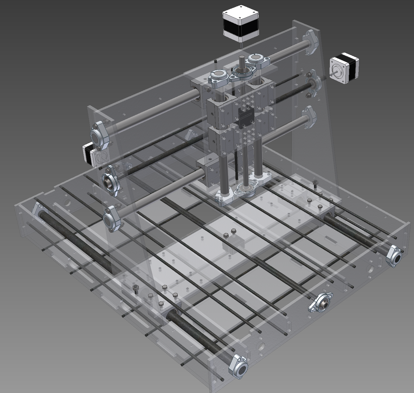
Fig 8. Almost full machine. It just lacks the ground plate for a work-piece (which will be covered by a sacrificial board)
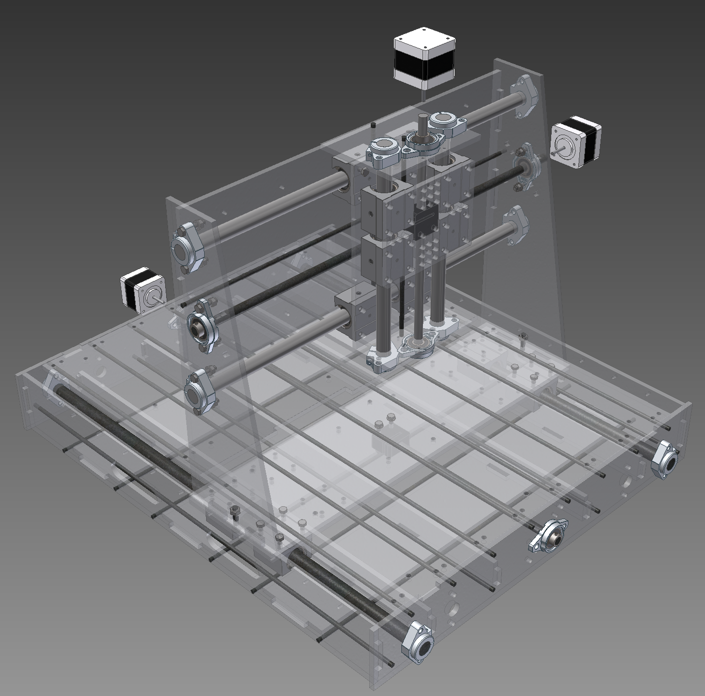
Fig. 9 - Ground plate added Apparently the ground plate is a bit larger than the work area of the laser cutter to which I have access to (plate is 600x450 mm but the laser is 600x400 mm) so I had to cut it in half. Left a 0.2 mm between the plates so for all practical purposes it should be pretty tight fit. The plates would be fixed to the threaded rods under them by zip ties according to the current plan.
Both side-plates have a row of little holes along the top edge which are intended for "something" that would deal with electrical wiring when the working part runs back and forth along the x-axis. I will think about it some more though. Probably some kind of cable channel, perhaps just a "U" profile attached there by small rivets.
A note about work area. It will be slightly more than A3 it seems currently. A3 is 420x297 mm and this one can have a work area of about 430x320 mm with approx 10 mm safety margins before hitting the physical constraints of the machine. However, the actual dimensions of the piece this thing would work on could be in the x-axis direction as long as you can support to be level and in the y-axis the constraint would be the width that can go in there so approx 450 mm although out of which you can probably access only about 320 mm in the middle width wise. This should be even feasible in practice with the usb microscope in the machine for setting the coordinate zero point on the X-Y plane with very high accuracy if I would, for some reason, be working with a piece which is longer. Not that I plan it to be of regular occurrence as it is probably still involve significant manual processing for making the G-code capable of handling something like that.
Discussions
Become a Hackaday.io Member
Create an account to leave a comment. Already have an account? Log In.