 Stefan Lochbrunner
For my first PSU build I used one of these cheap LED voltmeters that you can get from eBay for less than 2€. The ones I got have a measuring range of approx. 3-30V. The lower boundary is due to the fact that these meters measure their own supply voltage.
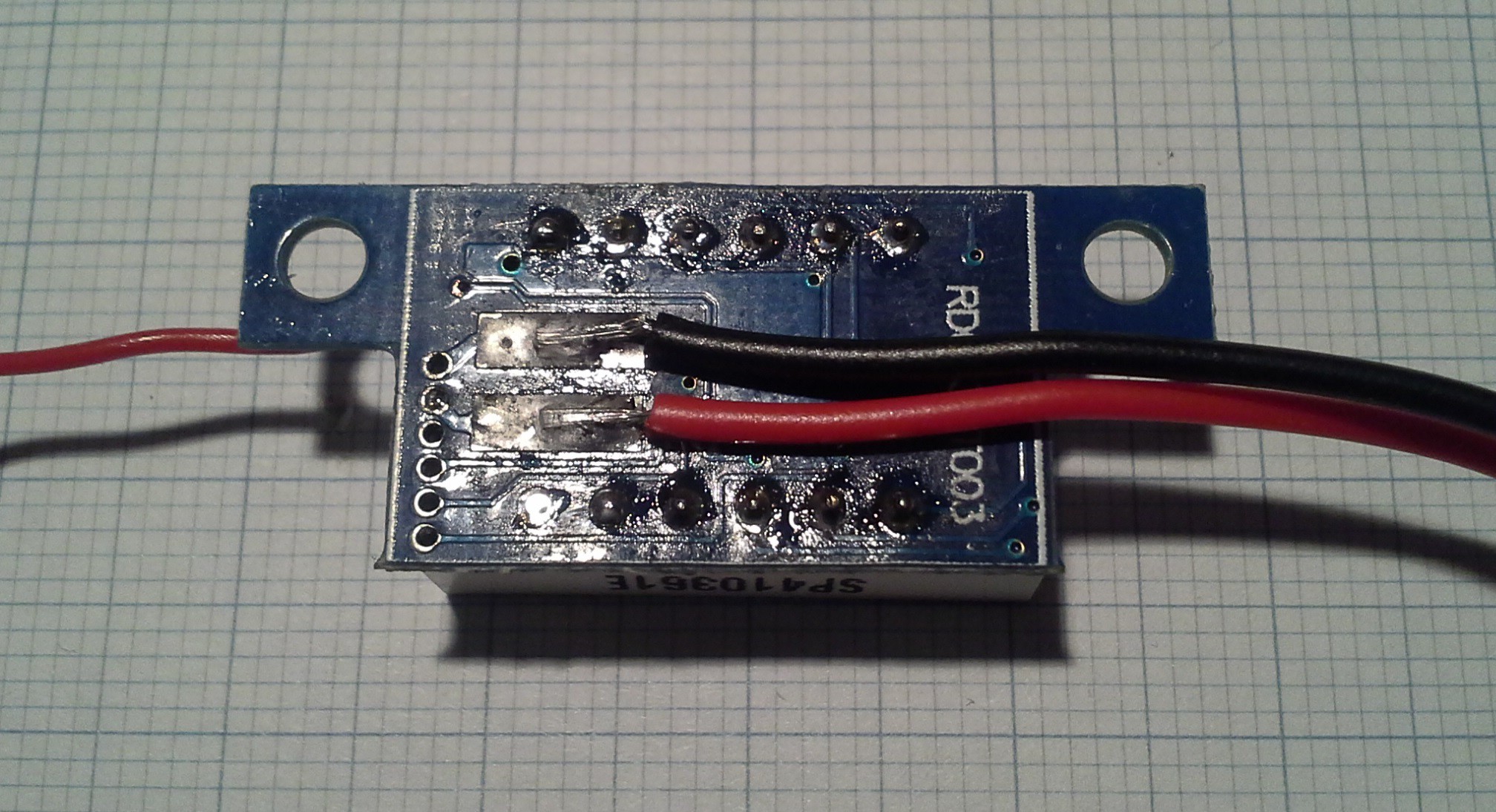
Unsatisfied with this lower boundary I analyzed the 2nd meter I ordered as a spare to see if there was something I could do. With only half of the PCB visible I first desoldered the display and in an attempt to view both layers of the PCB I put it on a lamp:
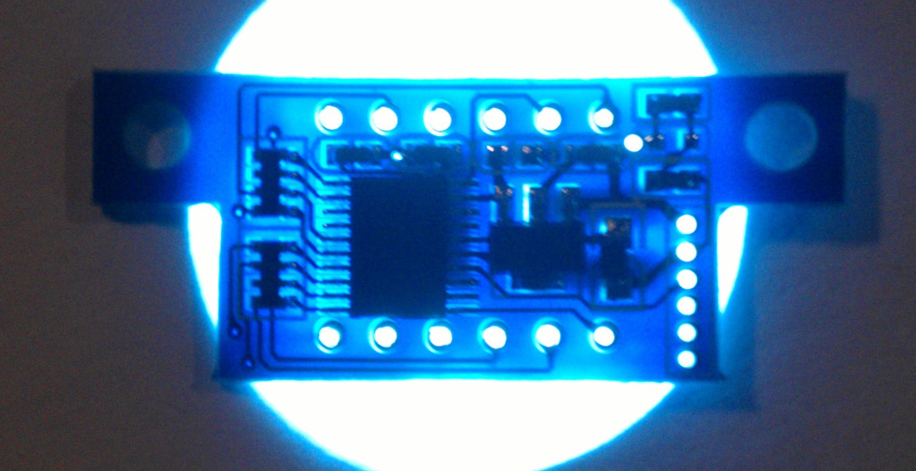
... with arguable success... looks nice though. However, it actually helped seeing the traces on the side I was looking at since the silkscreen concealed some of them.
Anyway. I could now follow the input voltage to the voltage regulator and to a voltage divider.
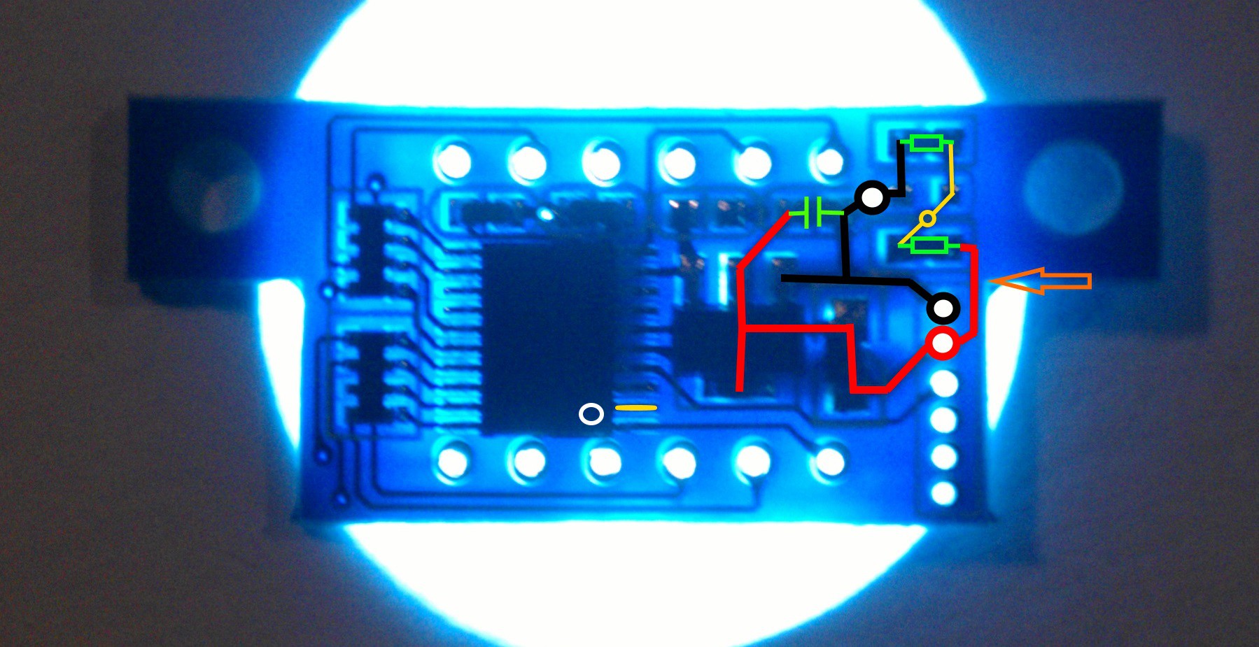
The center of the voltage divider (yellow section) first goes to the other side and then to another via under the MCU. Checking the continuity shows that it's going to pin 2 (with the marking for pin 1 being in the bottom right). In order to separate supply and measured voltage I simply cut the trace between the voltage divider and the supply voltage (orange arrow) coming from the other side and made sure the connection was severed. The first (high side) resistor of the voltage divider right above the orange arrow also made a good point to solder a wire to for the sense voltage.
With this voltmeter I was even able to perform this modification without taking off the display. Cutting the trace at the very edge was easy while soldering a wire to the resistor was more difficult.
In summary the basic gist is to first identify voltage regulator and divider, cut the trace and then solder an extra wire to the voltage divider. Depending on the model of voltmeter you have this might not be feasible without disassembly and on others where the components are on the the outside it might be even easier.
Discussions
Become a Hackaday.io Member
Create an account to leave a comment. Already have an account? Log In.
This variant is maybe easier to hack
https://hackaday.io/project/16097/logs?page=6
Are you sure? yes | no
So is the cheaper imitation I got: (non STM8 based). It even has the solder pad for separate supply and solder jumper for selection.
https://hackaday.io/project/7700-collection-of-misc-small-project/log/30822-cheap-voltmeter-from-china
Are you sure? yes | no
The small via directly above the six holes on the left (in your first photo) is connected to the mid-point of the voltage divider. You can scrape off the soldermask and connect your signal to that point (via a 75k resistor to match the 8k2 lower divider resistor). I found this easier than trying to connect to the existing resistor.
Are you sure? yes | no
Good point, I just preferred having no external components.
Are you sure? yes | no
I just ripped off the resistor where I soldered the sense lead on.... gnargh. But I found a cheap replacement on ebay that already has separate power and sensing for 1.29euros. I'm going to revisit the PSU stuff soon, but I will use an old notebook power supply this time.
Are you sure? yes | no
I'm happy to hear you're looking into it again :)
Too bad the resistor got ripped off. Was the voltmeter like this one where all the SMD components are on the same side as the display? If you know the value of the resistor you might be able to fix it since there are a couple of pads you could solder to. Some hot glue as strain relieve might also be a good idea.
But for that price you might as well just buy one ;) If you haven't ordered it yet you might also want to think about a dual volt & amp meter. Those cost more but it's a really handy feature to have.
Are you sure? yes | no
I was about to glue it, when I ripped it off moving the cables. I think it was a 3k9 resistor, the one you have mentioned for soldering the cable on. I have ordered that dual thing, too, but also 5 of the cheapos :)
Are you sure? yes | no
lol, that sucks :\
It's pretty handy to have some of these cheap meters on hand for times when a multimeter is overkill or just too bulky.
Are you sure? yes | no
so the orange arrow is your "cut here" and the sense connection would be on the cutted trace that leads to the voltage divider?
Are you sure? yes | no
Yes, exactly. I'll add it to the text. It was kinda late when I wrote it so thanks for pointing it out ;)
Are you sure? yes | no
we share a timezone ;) I was awake, too and was working on a schematic but wasn't really fit for it. ANyway, it's always best to put it in your own words, to check if you got it right..
Are you sure? yes | no