 Bud Bennett
Assembled the components onto the PCBs without a hitch. I soldered the back side first because I heat the back side of the board whenever I have exposed-pad parts. This gives a better chance to melt the solder under the part to properly connect the exposed pad. Hopefully, the parts on the back side won't fall off when the top side is soldered.
I found a small gotcha when checking for shorts on the back side. If you touch the DVM to the gate of the power FET and then measure resistance across the drain-source you will get a short circuit. This occurs because the DVM charges the gate of the FET above the threshold voltage and it will then appear to be a short circuit across the drain-source. I had to short the gate-source terminals prior to measuring for short circuits between drain-source terminals.
At this point the design appears to be fully functional. The prototypes look like this:
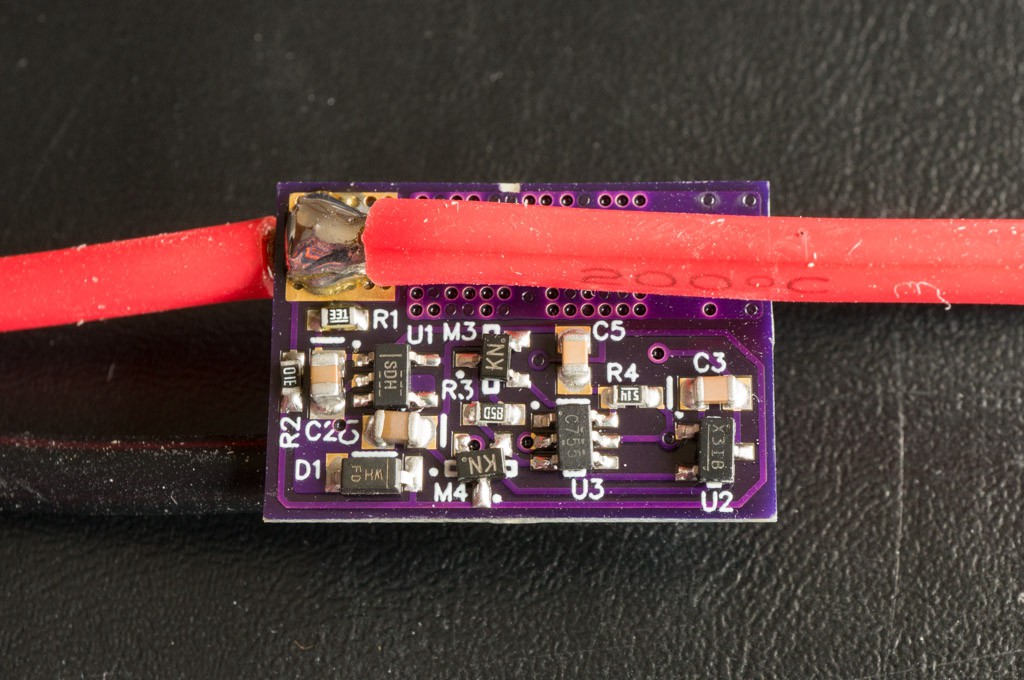
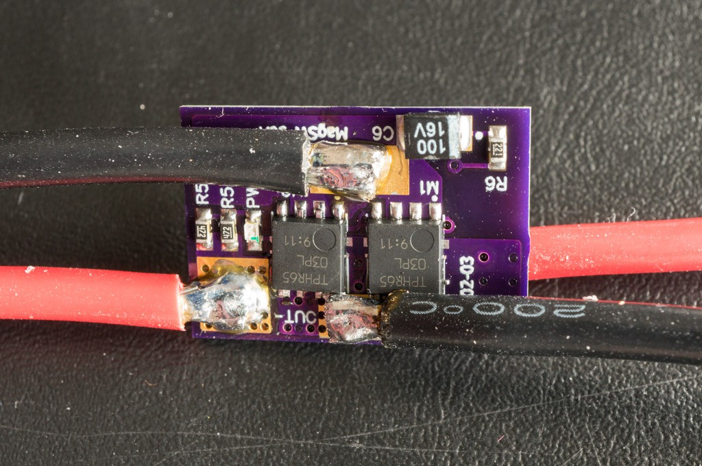
Those are 14AWG wires. I believe that 12AWG is the max size that the board will accommodate. 14AWG is rated at 34A for chassis wiring. If you think you will be averaging more than that, then the 12AWG is rated at 41A. It's all relative to power and heat -- use your discretion.
Test Results:
There aren't many parameters to test.
Off-state current vs. Voltage:
50µA @ 30V
46µA @ 25.2V
41µA @ 21V
37µA @ 16.8V
33µA @ 12.6V
29µA @ 8.4V
On-state Current:
9.5mA @ 25.2V
I soldered two 30AWG Kelvin leads to the PCB pads near where the wires were connected. The location of the Kelvin leads makes a big difference in the measured voltage drop across the FETs. Since I don't have any precision/programmable load that can generate 40A I used my Tundra airplane's motor and ESC to provide the load. The Tundra draws very close to 40A during full throttle from a near fully charged hefty (5Ah) 3S LiPo battery.
Voltage drop across FETs during 40A load: 13.5mV. That's 0.34mΩ switch resistance. With a 40A load the switch will only dissipate about 0.54W. It should be able to handle this load continuously without overheating.
The 40A load current did not create enough magnetic field to turn off the magnetic switch. The switch seemed rock-solid to me during testing.
Next Step:
Test the switch with a >50A load with a 5S or 6S battery. I'll need a friends help for that.
Discussions
Become a Hackaday.io Member
Create an account to leave a comment. Already have an account? Log In.