I assembled the 30A mag switch PCBs without issues. I expected some problems with the M1 & M2 PowerPak packages, but for some reason they always solder up just fine. I measured about 22µA of off-state current with 6V < VIN < 20V. Pretty much the same as the 4A boards. With 5A applied load current I measured 1.1mΩ switch resistance -- spot on the design target.
The bad stuff happened when I hooked the switch up to a 30A_ESC/Radio/Motor. The switch disconnected itself when the current exceeded 16A. Bummer. I remembered a warning from a colleague at LTC/ADI about "scary currents" that could affect the hall-effect switch, so I went online and found this website calculator for magnetic field strength vs. current through a wire. It turns out that the magnetic field strength 1mm distant from a wire carrying 16A is about 32 Gauss -- very nearly the trip point of the hall effect switch. Stupid me.
In order to test out this theory, I desoldered the hall-effect switch from the circuit and located it onto a separate board with 2 inches of wire. Problem solved. The switch is now apparently immune to current flow.
But I could not reproduce the same problem as before by holding the hall-effect sensor near the current carrying wire as high currents flow. That was somewhat disconcerting, but par for the course.
POOF!
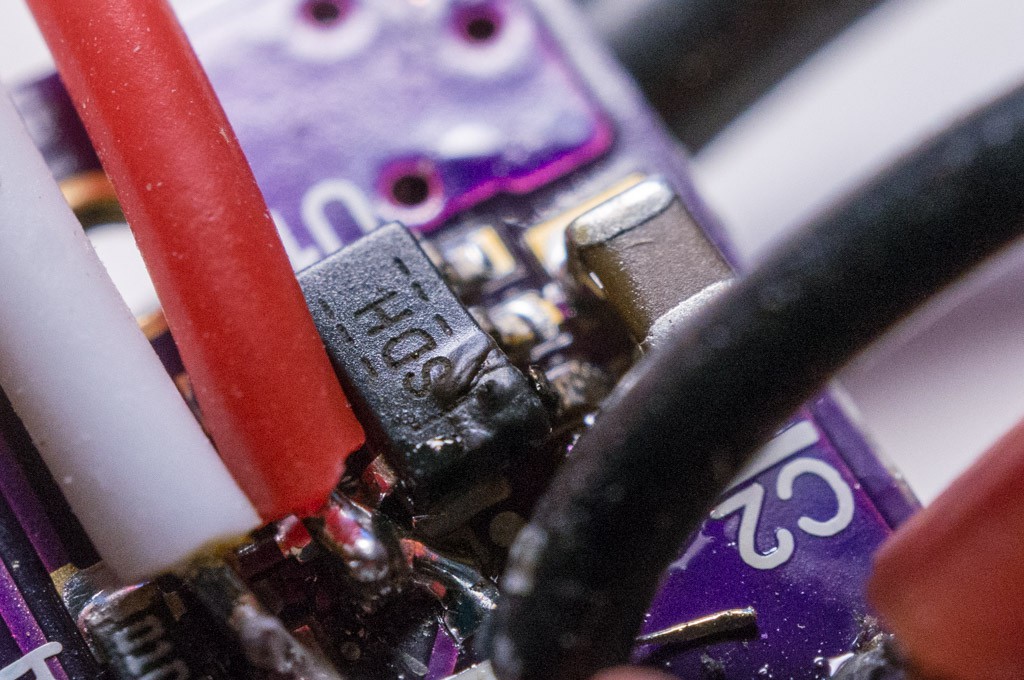
I decided to use a 4S battery and a 60A ESC to generate a current above 30A to test the circuit. When I connected a fully charged (16.8V) 4S LiPo to the input the circuit lets some of its magic smoke out. After all the cussing ended I was able to determine that the TPS70950 LDO had apparently latched up -- the current was enough to fuse the VIN lead open:
It is apparent that a 30V rating is not enough to prevent inductive transients damaging the LDO. The second pass, and all the other mag switch circuits, will have a protection resistor to prevent this in the future. After replacing the LDO and the hall-effect device, which was also damaged by the event, I jury-rigged a 330Ω protection resistor in between the LDO and the battery. I plugged/unplugged the battery many times to see if there was any remaining tendency to smoke, but the circuit doesn't have that problem anymore.
High Current measurements:
With load current 35A, the voltage across the switch was 40mV (that's 1.1mΩ). Power dissipation is only 1.3W, which should not be a problem for a board even this small. I repeated the measurement with 20A load current and got 22mV across the switch, and the same switch resistance. No changes required.
So here's the plan:
Add a 330Ω protection resistor between B+ and the LDO input.
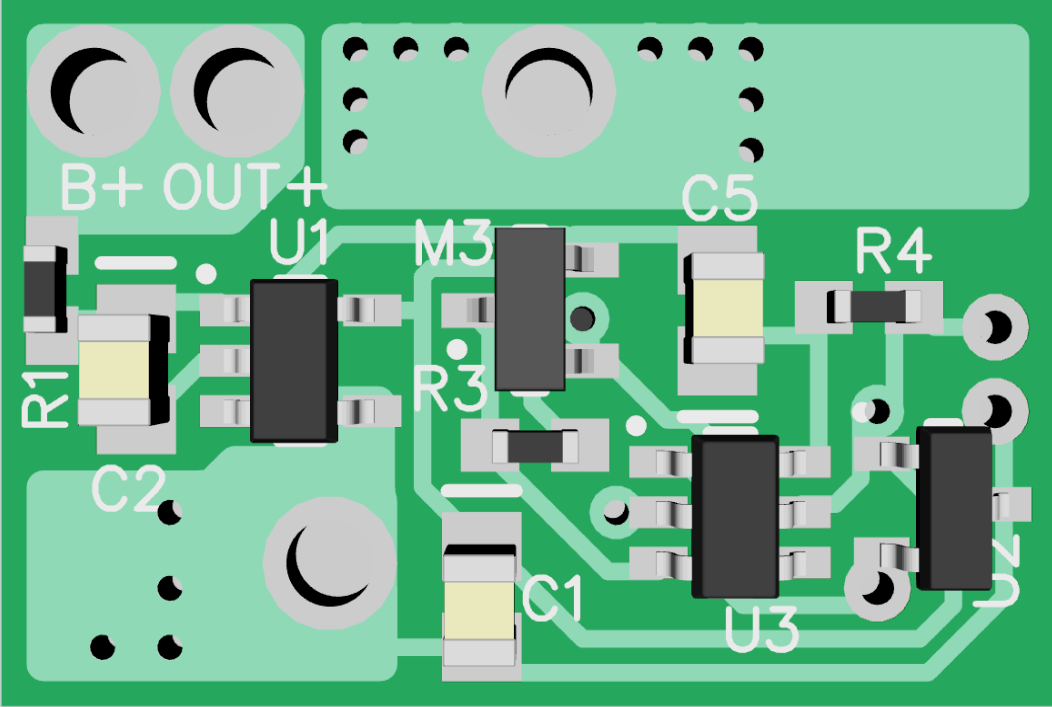
Change the layout to move U2 as far from the current carrying traces and wires as possible. Here's the proposed topside layout (the bottom side did not change much):See that U2 (the hall-effect switch) moved to the bottom right side of the PCB. I measured 4mm from the high current traces. A wire carrying 50A generates 25 Gauss at a distance of 4mm. The board area increased, but not materially.
Change the hall-effect switch to increase the trip threshold. The S-5716ACDH2 component is specified with a typical threshold of 45 Gauss vs. 35 Gauss for the AH180 part. The minimum specified threshold is 25 Gauss.
Use a magnet with higher field strength to compensate for the increased hall-effect threshold. I ordered a few 6mm dia. x 10mm length N52 Neodymium magnets to use in the application going forward. These new magnets have significantly higher B-field to compensate for the increased threshold. Another website yields useful calculations.
There may be some users that want to locate the hall-effect sensor away from the main circuit board. I added pads to allow leads to be soldered instead of mounting the sensor on the board.
The change from the AH180 hall-effect sensor to the S-5716 sensor changes the way that the switch works. Previously, the switch would change state when the magnet was removed. Now the switch changes state when the magnet is applied. This should provide more immediate feedback to the user.
The project details have been updated with all of the changes. I will wait a few days before ordering new PCBs.
 Bud Bennett
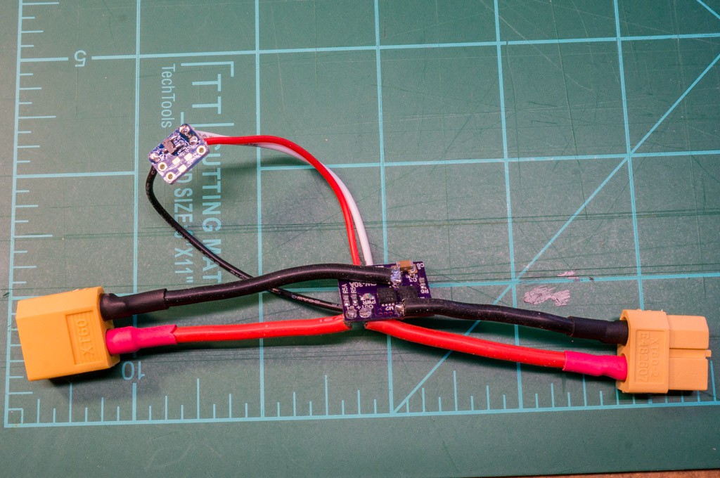
Discussions
Become a Hackaday.io Member
Create an account to leave a comment. Already have an account? Log In.