 Bud Bennett
After destroying the LDO on the 30A mag switch board I decided to revisit the protection circuitry for all of the other boards. The 4A circuit is a copy of the 30A board so it should be OK. The problem is with the BEC version. The switching buck converter requires low ESR ceramic caps at the input. This causes ringing when the battery is connected to the board -- potentially damaging or destroying the circuits that are connected to the battery terminal.
I investigated protection devices like TVS diodes or Zener diodes to clamp the inputs, but they did not have close tolerances that would prevent the input voltage from exceeding the 20V abs. max. VIN value for the RT6255 switcher. I decided to dust off LTSpice to see what was happening and look for possibly a simpler, less expensive solution. Here's the test schematic that I used:
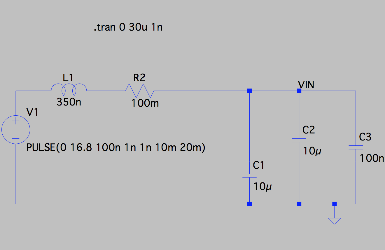
The inductance is just the wire leads from the battery to its connecter and then from the BEC connector to the PCB. I measured a fairly constant battery wire length of 4 inches for all of my batteries. If I add 1.5 inches for the mag switch leads then I get a total length of wire connected to the input that is approximately 11 inches (doubling the wire lengths to accommodate both the positive and negative leads.) I then visited this website to calculate the approximate inductance of the wires leading from the battery to the PCB -- which is about 350nH, represented by L1 above. Of course, there is some variation in these values, so I varied it over a reasonably wide range (300-500nH) to accommodate reasonable scenarios
I also measured the resistance of nearly all of my stock of LiPo batteries. I found that it ranged from about 25mΩ to over 100mΩ. If you're interested, the Multistar 1.6A 3S 40C LiPo batteries had the lowest resistance and the cheap Chinese NoName batteries tended to be at the top end of the resistance range. I figure the middle of the pack is about 50-60mΩ. This is represented by a portion of R2.
C1-C3 are the input capacitors required by the RT2255 buck switching regulator. I gave each of them 5mΩ ESR ( variation around this value did not have much effect).
This is what the input transient looks like without any circuit changes made for protection and R2 = 25mΩ for the battery resistance:
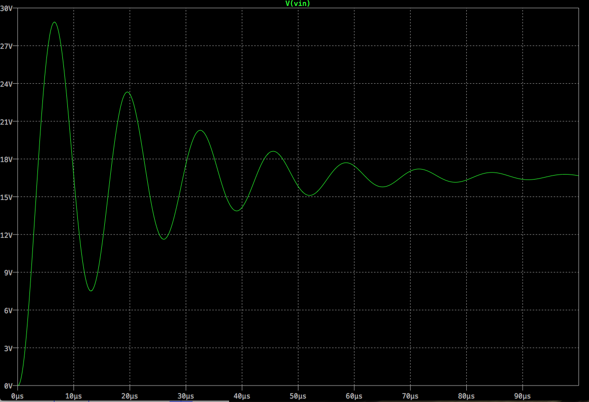
That first peak of nearly 30V would smoke the switcher IC. The peak transient waveform ranged up to 24V-27V, depending upon the values of C1-C2 and the associated ESR, the inductance in the lead wires, and the battery resistance.
My first thoughts were to add a snubber -- a series R and C across the inputs. This could be just a tantalum capacitor with an appropriate ESR value . The problem I found was that the capacitor had to be greater than 100µF and the series resistance (or ESR) around 100mΩ. I could not find a reasonable size ceramic 100µF capacitor with a 25-50V rating, or a tantalum with <500mΩ ESR. The solution for the snubber to work was to put 15x 10µF ceramic caps in parallel -- so I abandoned this idea in favor of adding resistance in series with the input.
R2 now represents the battery resistance and also a discrete resistance added in the circuit, R10, for the specific purpose of transient suppression. I won't bore you with the details, but I found that the value of R2 needed to be between 100mΩ and 150mΩ to keep the peak of the transient waveform below 20V (the absolute maximum VIN value for the RT2255 IC). C1 and C2 need to be increased as well -- even with a 50V rating the capacitor value decreases by 40% with 17V across it -- so the simplest solution is to stack two 10uF/50V caps in the place of one. This would not be a solution for high volume production but I can accommodate it easily when populating the board manually.
Here's a typical simulation waveform result showing the improvement:
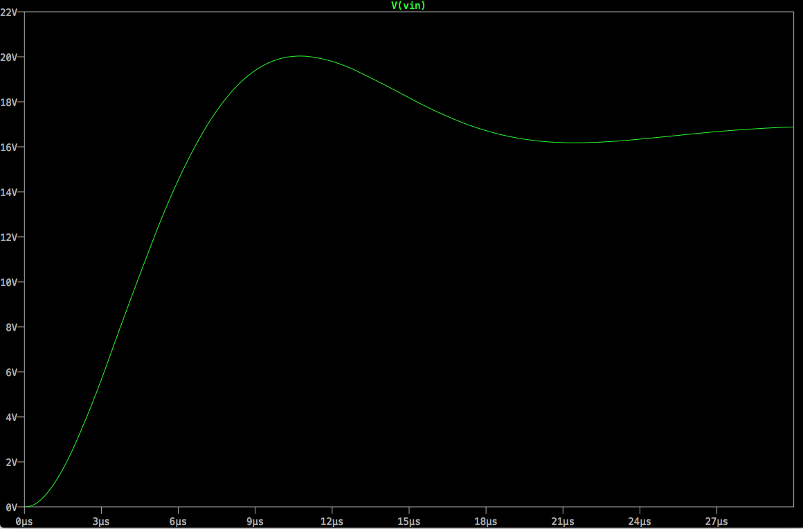
R10 needs to be a power resistor. When you insert 100mΩ of resistance into the input lead of a buck-mode switching regulator, that resistor is going to dissipate power. My calculations indicated that I needed a resistor capable of dissipating 1W. I found some surface mount 1W resistors on eBay in a 2512 package. I ordered 50mΩ, 75mΩ and 91mΩ values. This is a relatively huge component, but it will fit nicely as the only component on the back side of the board. I also ordered some 22µF 25V X5R 1206 ceramic caps in case the 10µF ceramics were not large enough. They're relatively cheap and will just add to my inventory if not used.
I haven't received first pass BEC version PCBs yet. These changes will wait until after I evaluate the first pass prototypes before ordering new PCBs.
Discussions
Become a Hackaday.io Member
Create an account to leave a comment. Already have an account? Log In.