 Boolean90
First Stage (Audio Modulator):
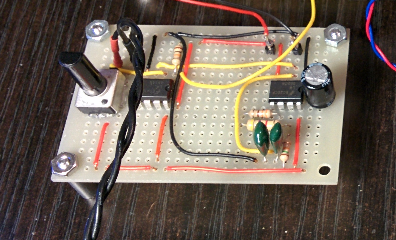
This class D amplifier takes in a mono audio signal as the input to an lm393 comparator. The other input of the comparator is a 60Khz triangle wave using a 555 timer triangle wave generating circuit I pulled off the web. The resulting output of the comparator is a square wave with a duty cycle that is proportional to the audio amplitude. This signal can be used to switch the voltage across a speaker using a Mosfet bridge (and a low pass filter in series with the speaker). Ideally, in class D amplifiers, we would want a faster modulating frequency of hundreds of kilohertz for better reproduction of sound. Since this is a subwoofer amplifier will have a frequency cutoff at ~ 1Khz, A 50Khz carrier frequency is plenty fast to recreate these low frequencies. The lower frequency also means a lower switching speed which reduces energy losses in the output mosfets in the next stage.
Second Stage (Output H-bridge with shoot-through protection):
This is the "business" stage of class D amplfiers! Now that we have a square wave from the first stage, we can use it to switch a big load, like a large (2-8ohm)subwoofer. The square wave is passed into an inverter IC in order to create two opposing square waves to drive each side of the Hbridge. Both of these signals are passed through inputs of separate XOR gates. with one input of each wave having a series RC highpass filter. This creates a delay in the rising edge of each wave proportional to how long it takes the RC circuit to charge. I simply googled "XOR dead time circuit" to learn how to do this.
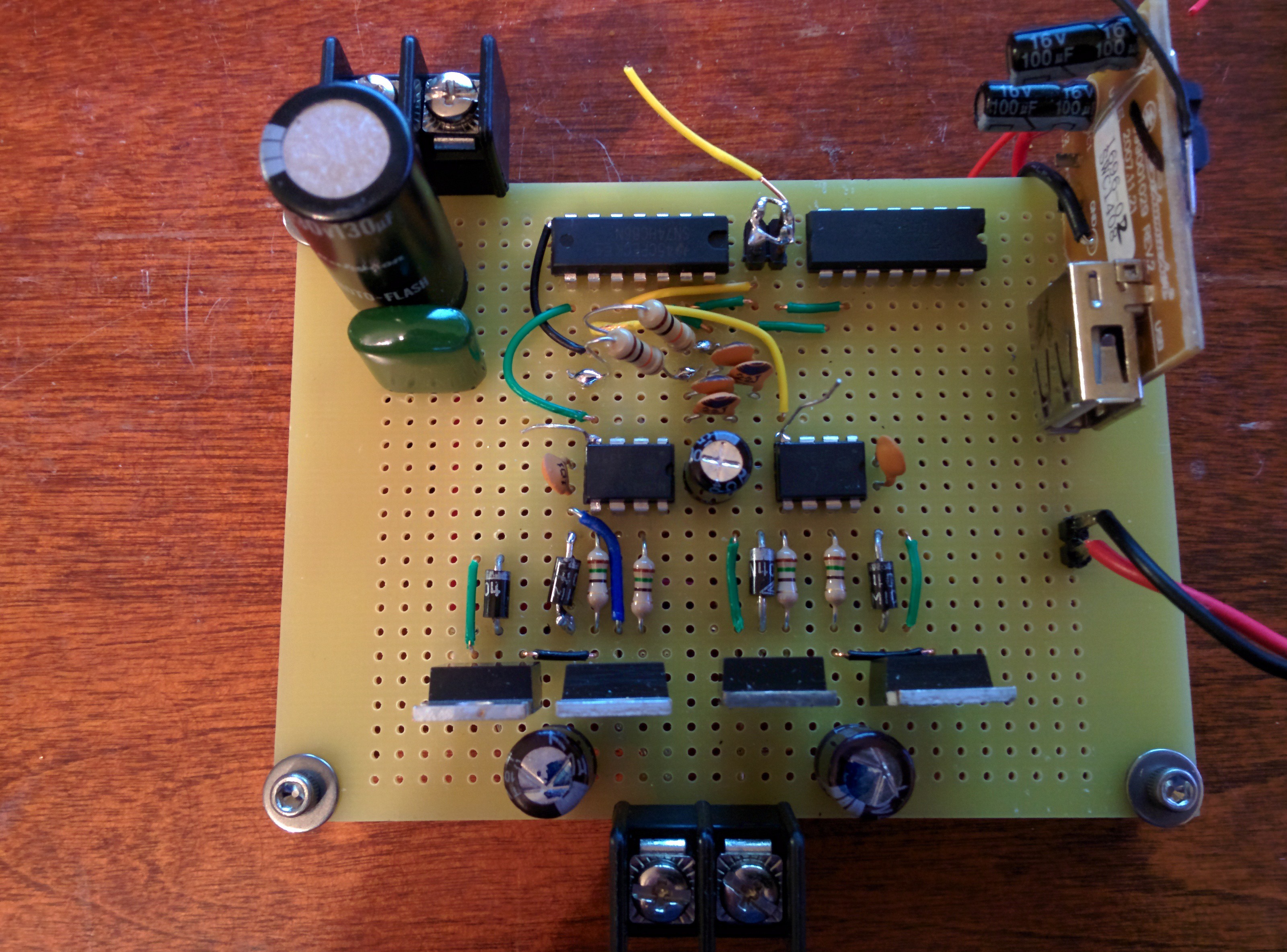
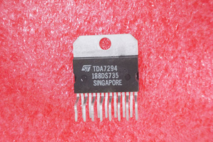
These signals are then passed into an IRS2110 Gate driver to control a Mosfet Hbridge. Because class D amplifiers work by switching Mosfets fully on or fully off, switching losses are minimized and efficiencies are high. Therefore, there was no need for me to heatsink the FETs on this bridge seeing as they stayed cold.
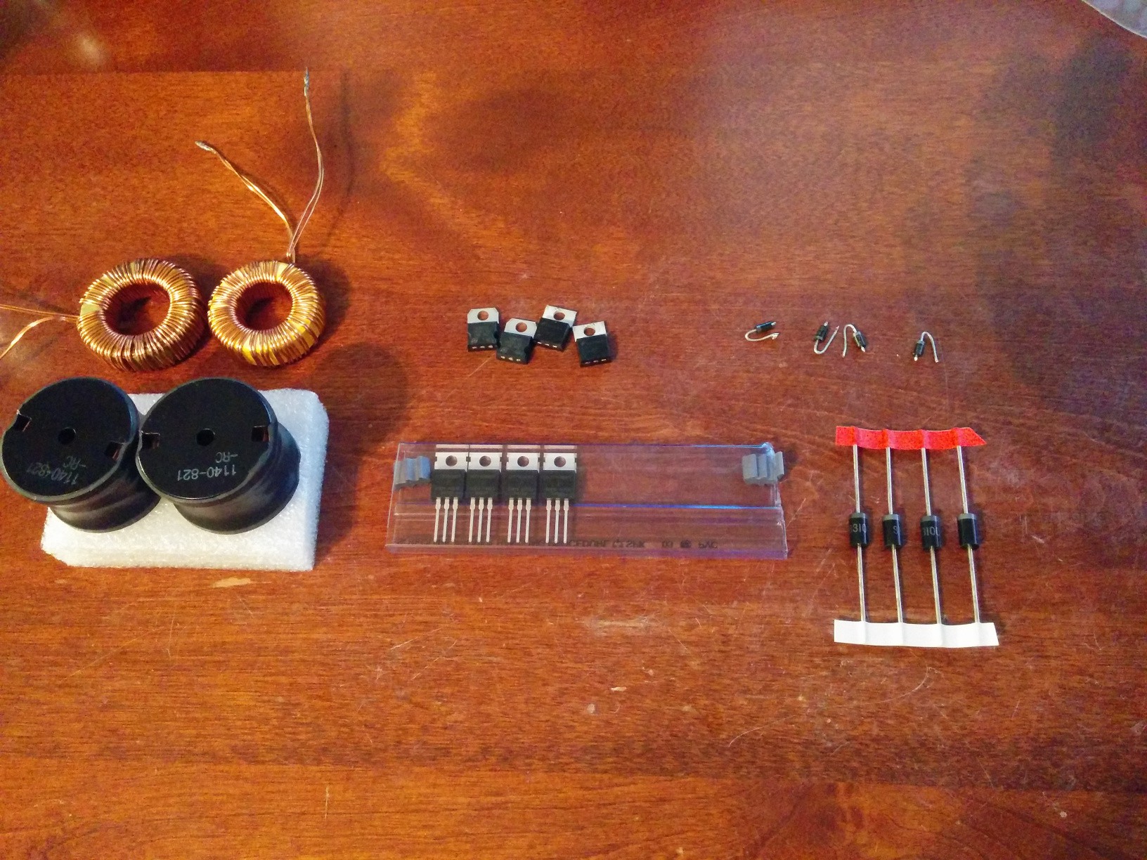
The output of the Hbridge cannot be wired to a speaker just yet! The signal on the output of the H-bridge is still a square wave at a high frequency. We need to filter out this fast switching wave to be left with the slower frequecy created by the varying duty cycle (the audio we want). I did this with two series 800uH inductors on either side of the speaker/subwoofer and a 1uF capacitor across the speaker (not sure on exact values, I played with it until it sounded right). The inductors can be seen to the left in the image below (the black inductors are replacing the ones I hand wound which were TERRIBLE at filtering out anything):
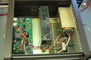
Third Stage: The Power Supply
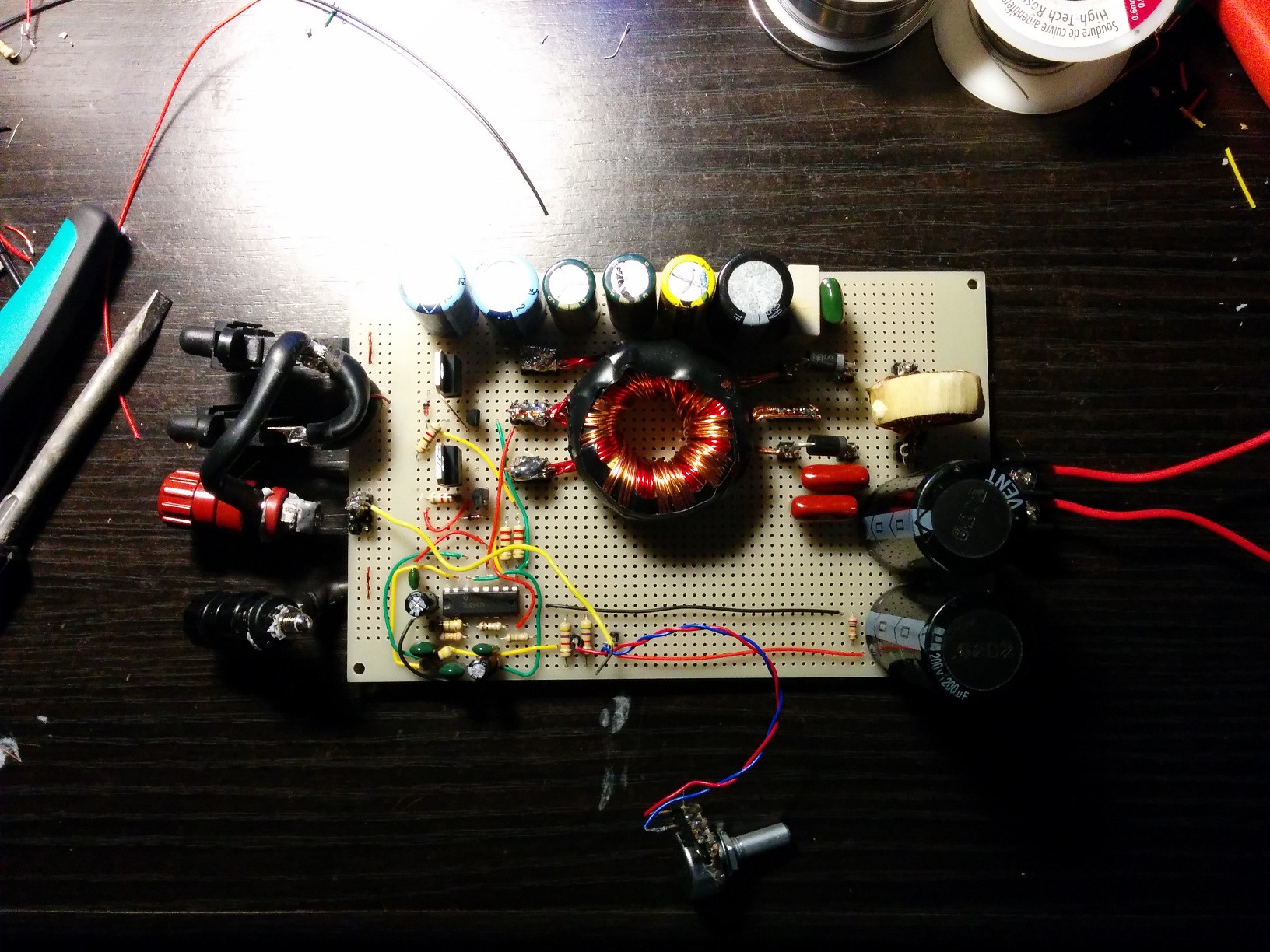
This was my first try at a push-pull converter type power supply and let me just say, there were many failures before this worked! The biggest issue I had was the winding of the transformer.
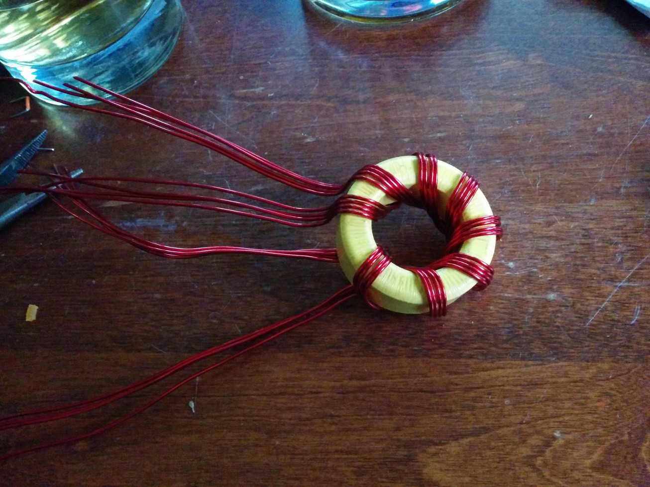
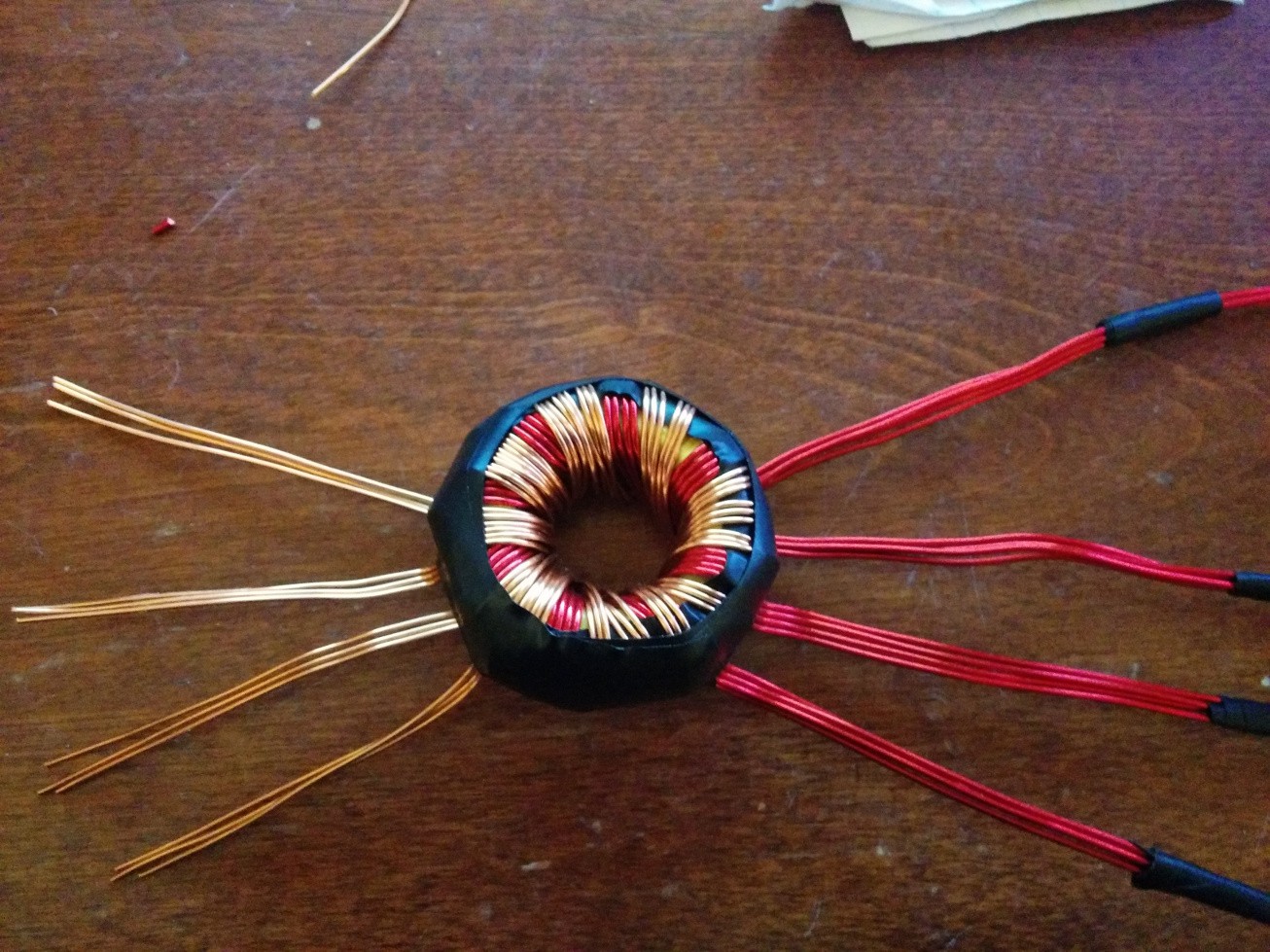
The circuit uses a TL494 PWM controller IC to regulate a constant output voltage by varying the duty cycle on two Mosfets at the primary sides of the transformwer. The toroid consists of two primary windings using 4 parallel strands of 18AWG enamel wire (4 turns). The two secondary sides are 3 parallel 20AWG enamel wire wound 8-10 times. The output voltage I regulated the supply to was 25V as a maximum with the car battery's 12-14.5V as the input (varies with the alternators charging voltage). This voltage will "sound" as loud as a 50V supply on a Half-bridge class D amp since the Full bridge class D amplifier will switch 25v in both directions across the subwoofer, giving us a peak to peak voltage of 50V from a 25V supply.
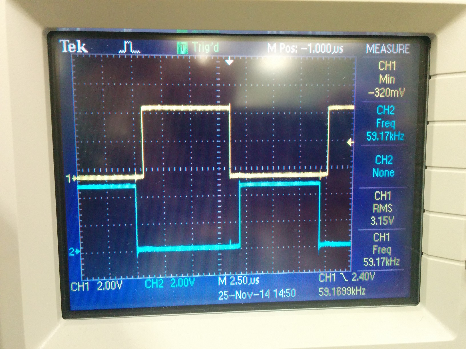
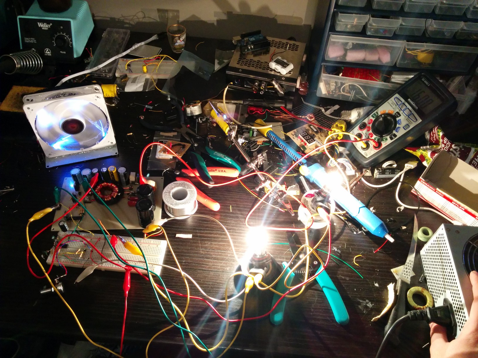
This picture shows a stress test I performed by lighting two car headlights in series:
Final touches to the power supply board include integrating an over temp circuit using an LM35 temperature sensor and a voltage comparator. The LM35 output is compared to a voltage of 0.80V which translates to 80 degress Celcuis. If the temperature of the primary side Mosfets for the power supply passes this point, the comparator will trip and disable the gate driver-turning off the output. I also have added...
Read more »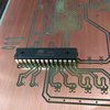


 Electroniclovers123
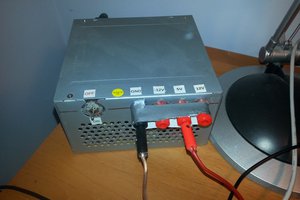
 Quinn
Quinn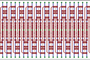
Hi, where did you found the toroid core?
i have a gray core and it kinda works. i mean it does output some power but it cannot keep the voltage stady. it drops from 30V to 4 or 5V with a 10Ω load. i guess it's the cores foult. where can i find a core that works for this job? (except thoose ATX EE or EI transformers )