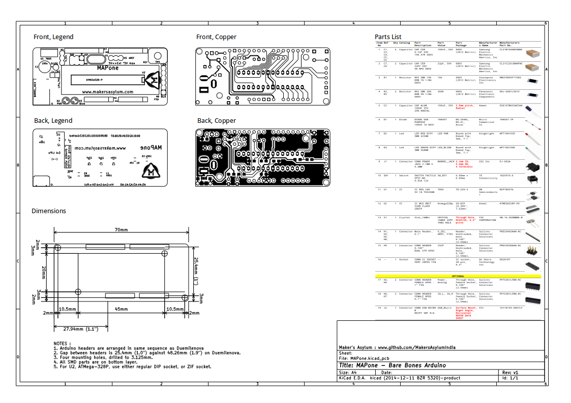
Close
0%
0%

MAPone

basic, bare bones, cheap, Arduino clone to help support Makers' Asylum maker space in Mumbai, India

Similar projects worth following
MAPone (Makers Asylum Project #1) is an experiment we are trying out at Makers' Asylum - a maker space in Mumbai. The board itself is a simple Arduino UNO clone, with the same pin-outs, but a smaller, breadboard friendly footprint. It has SPI and Serial UART (FTDI) headers. Can be powered via SPI, Serial, up to 12V barrel socket (with reverse protection diode), 5V micro USB or 2-cell LiPo (7V2). There's a power LED and a Blink LED on D13. The ATMega328P can be soldered directly to the board, or via a DIP socket. Further, it's possible to install a ZIF socket and then use it to bulk program a bunch of micro-controllers.
But more than the engineering aspects of it, what we are trying to do is find a means of supporting and running our maker space. So, the funds we receive from MAPone sales will go (100%) towards the running of the maker space, buying tools etc. To achieve this , we will most likely run a crowd-funding campaign. The design itself is ready and tested and works.

View all 2 project logs

  • 1
    Step 1

    Build instructions are quite straight forward, and the board can be assembled within an hour by anyone with basic soldering skills. To that end, we have also got about 10 SMD parts that go on the board - just so you can hone your SMD skills. These are all 0805 components, three resistors and seven capacitors, all on the back side of the board. Assembling the rest of the parts should be quite simple. The video provides a walk through of the design and assembly process.

  • 2
    Step 2

    Parts list and board details. PDF of this file is available in the git repo.

  • 3
    Step 3

    NOTES:

    1. Assemble the parts in the order in which they are listed on the assembly drawing.
    2. Cap C2 is polarized - verify before soldering
    3. Diode D1 is polarized and mounted vertically - verify before soldering.
    4. LED's D2, D3 are polarized - verify before soldering.
    5. LED's are sensitive to heat. Hold the leg with a plier and then solder (plier acts as heat sink). Do one leg, wait for it to cool down, then do the other leg.
    6. Regulator IC U1 is polarized - verify before soldering.
    7. In place of IC U2, solder it's corresponding SOCKET (or ZIF socket). Do not install the IC until smoke test is done (see below).
    8. Crystal X1 is non-polarized - goes either way. Or a 3 pin resonator can also be used (in which case, capacitors C7 and C8 are not required)
    9. Break off and solder Male headers as follows :
      1. H1 = 3 pins
      2. H3 = 2 pins
      3. H5 = 3 pins
      4. H8 = 6 pins
    10. Break off and solder Female headers as follows :
      1. H2 and H4 are combined as a single 13 pin header. Using a plier, remove the 7th pin from the female header and then solder H2/H4 as one piece.
      2. H6 and H7 are combined as a single 17 pin header. Using a plier, remove the 9th pin from the female header and then solder H2/H4 as one piece.
    11. Female headers are marked as optional, but can be soldered to allow easy connections to the MAPone.
    12. Make sure all parts are soldered in good vertical orientation, especially all Headers. If required, use paper masking tape to hold parts in place while soldering.
    13. TWO Jumpers (Shorting Links) are needed for headers H1 and H5.
    14. For H1 Jumper, refer legend on back side.
    15. For H5, install jumper towards "5V" marking (near X1)
    16. This completes soldering.
    17. For Programming, a USB<>FTDI Cable is needed.
    18. Make sure color codes match when connecting 6 pin header to H8 (GRN / BLK).
    19. Connect other end to a PC USB or 5V Wall wart.
    20. If PWR Led D2 lights up, and you don't see any thing burning or smoking - Rejoice. Your board has passed the Magic Smoke Test.
    21. Before installing the IC U2 on board, the Arduino UNO bootloader needs to be programmed on it. You need one Arduino and one MAPone (ideally with a ZIF socket)
    22. If the ATMega chip is loaded with bootloader, it can be installed on MAPone. Remove Power. Install IC U2 with correct orientation. It may be necessary to press flat the pins a little bit to make then fit the IC socket.
    23. IMPORTANT : The Board can be Powered in several ways : via FTDI, via external 12V barrel socket, via USB-Micro connector or via the female Header Pins. When using FTDI or female header pins, DO NOT use jumper on H1. When using 12V via barrel socket, install Jumper on H1 facing to U1. When using USB-Micro, install Jumper on H1 facing to J2.

View all 3 instructions

Enjoy this project?

Share

Discussions

Similar Projects

Does this project spark your interest?

Become a member to follow this project and never miss any updates