 classicrockfanatic88
Taking the Edison approach to designing my mold, I ultimately revised and printed five different iterations. As a machinist I'm more of a maker than a calculative designer, so it was super helpful to work out a 3D printed solution for creating a working part. If not for the ease and cost effectiveness of printing, these molds would have been taxing to produce by standard machining convention. I do have some other projects that may utilize this process during their work, and hope to add some future insight to this page.
The Process:
My first attempt to create a 3D printed rubber boot was actually a complete failure. In this instance I was refurbishing the drive train on my 1972 RV and found that the master cylinder boot was completely torn and rotten. Upon later inspection and attempted re-honing of the master cylinder, I found that the entire unit was shot. Luckily I was able to source an entire new cylinder with replacement rubber, but still my attempts to refurbish this unit started me down the path of cast silicone molding.
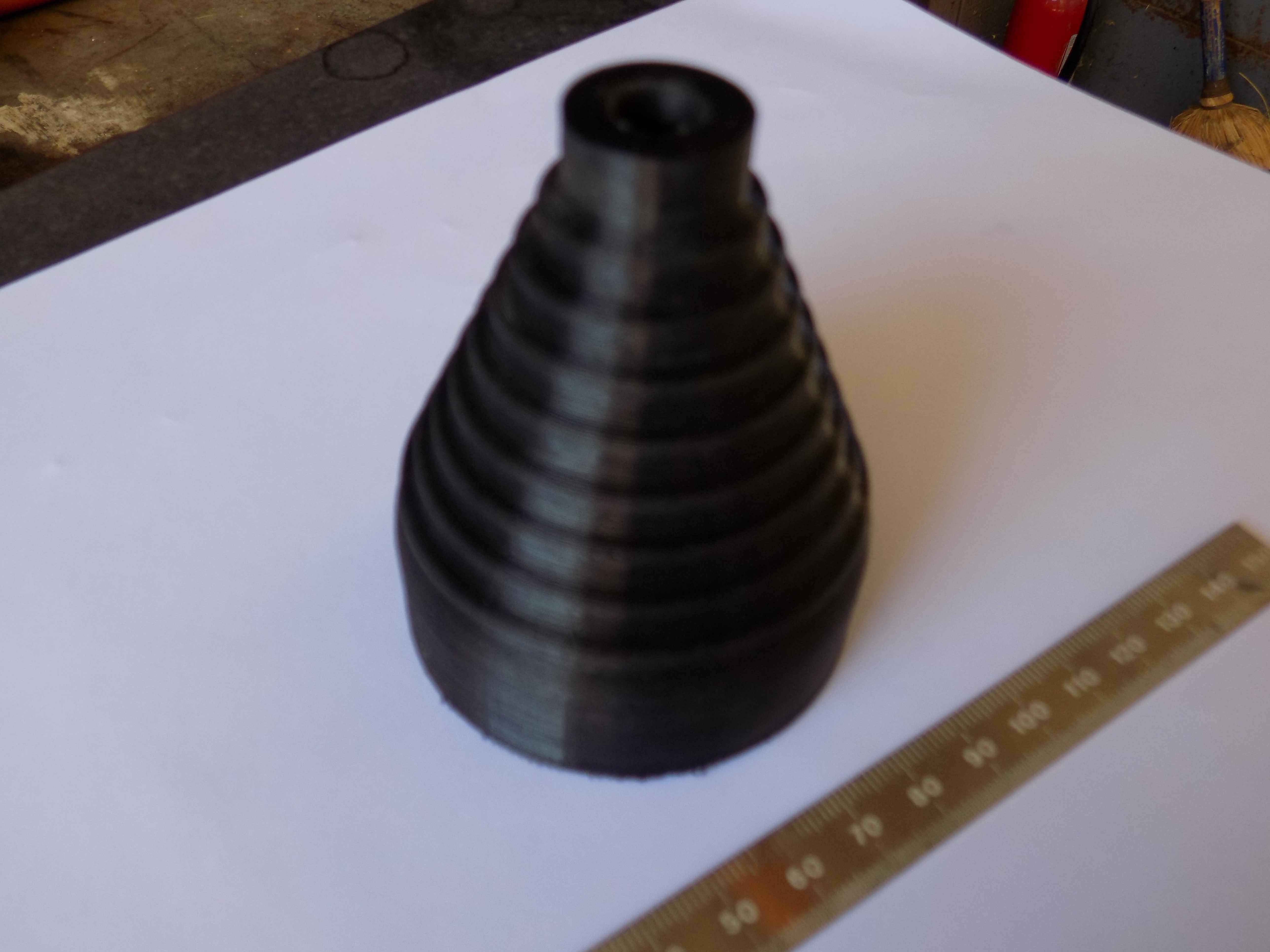
My original goal was to directly print a master cylinder boot that could expand and contract with the movement of the pusher shaft, just as the original part does. The original part has many horizontal shelves that allow the rubber to move without tearing, but for a 3D printed part this was a challenge. The plan of attack was to modify my part geometry to emulate a pyramid, and hopefully allow for an accordion style body that as 3D printer friendly shape. This design actually seemed to work except that I couldn't achieve any real durability. Even the best of my boot prints seemed to fail after a few dozen cycles of use. The final nails in the coffin for this attempt was the consideration of heat resistance that should be necessary for a component sitting so close to an engine. Since I ultimately procured a new boot with the new master cylinder, I marked this attempt as a fail, but still kept toying with the idea of how to produce a 3D printed piece of rubber that wouldn't fail so quickly in an industrial environment.
Another Failure?
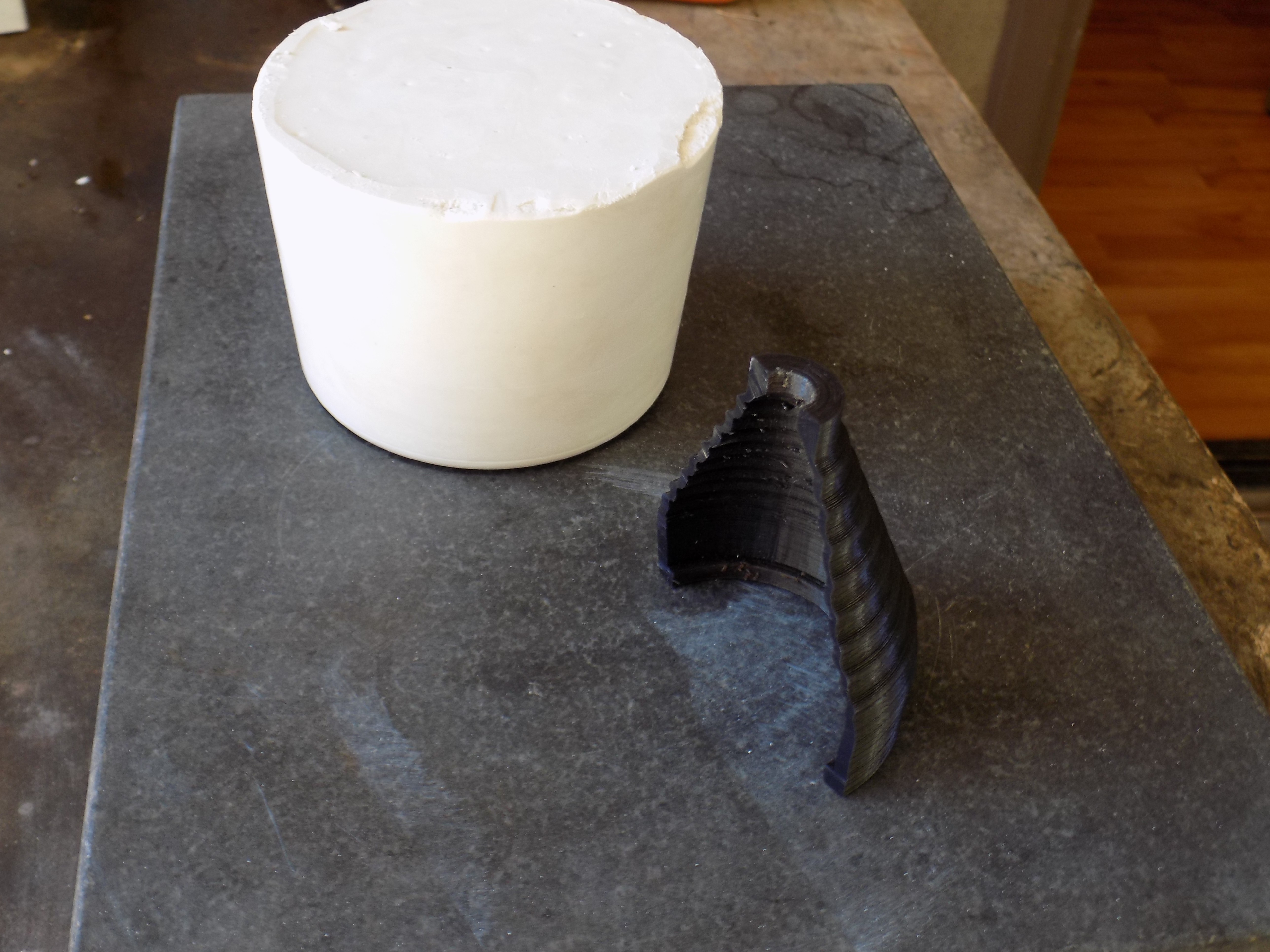
After finding that I wouldn't need any of the master cylinder boots that I had printed, I decided to try a post process heat treatment to improve the durability. Seeing that all my part failures were due to layer splits, my target was to somehow in essence, anneal the part. That is, bring it up to a temperature where the plastic can reform into a more consistent molecular blob ( real sciencey word ) without the mechanical lateral layer definitions. The well known problem here is that heating up the entire printed part will cause it to warp and deform. Therefore I tried to encase an over extruded part completely within a piece of plaster of paris, then bake. My own attempts at this were failures, but I'm still not fully convinced that this wouldn't work if properly carried out. The biggest problem encountered for me, was the lack of heat generation. Apparently baking plastic inside is not appealing to some, and the portable toaster oven I used didn't have enough juice ( or maybe time) to liquefy my part. I took care to keep half of my boot aside for a control, but the samples I took in my trials still showed clear layer boundaries in the profile.
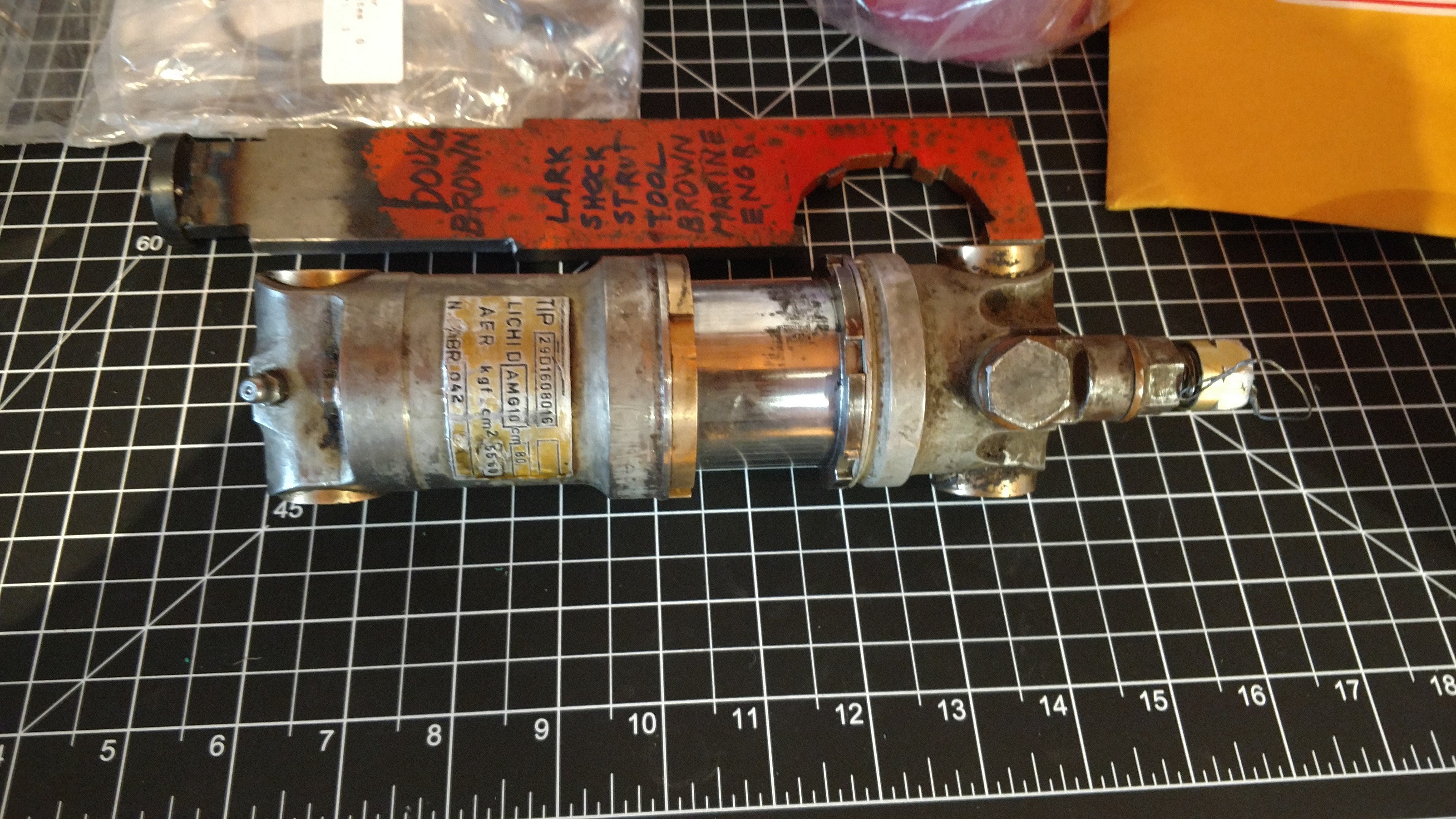
After finishing up my master cylinder work, and realizing I had no need to really make a good boot anymore, my interest slowly diminished. It wasn't until later, while working to refurbish a 1978 Lark landing strut ICA -IS-28, that I realized could take another swing at boot building.
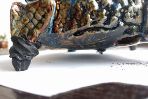
For this latest attempt at boot building I opted to cast a silicone mold. The reasoning being that silicone, while although not available as a filament, has excellent thermal and elastic properties. In this case, since there was no original boot to base geometry on, I also had to play around with different shapes and sizes before I had any success.
There have been a few...
Read more »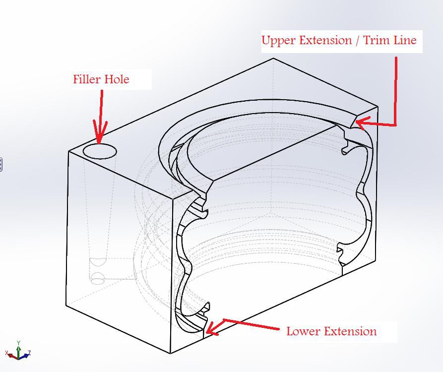


 UkiyoWeee
 Greg Stephens
 Brien Allison
Might be worth some kind of surface finishing on the 3D printed part to improve the roughness of the moulded boot. Maybe acetone polishing?