 Peter McCloud
Last time I had shown the Trinket Pro connected with the LCD. Since then I completed connecting the instrumentation amplifier (speaking of which, if you want to learn about instrumentation amplifiers check out this great hackaday article. and the load cell. Luckily it's all breadboard at this point because I forgot a lines at first, but after some trouble shooting I was able to straighten it out. Here's a picture of the hardware with one of the load cells.
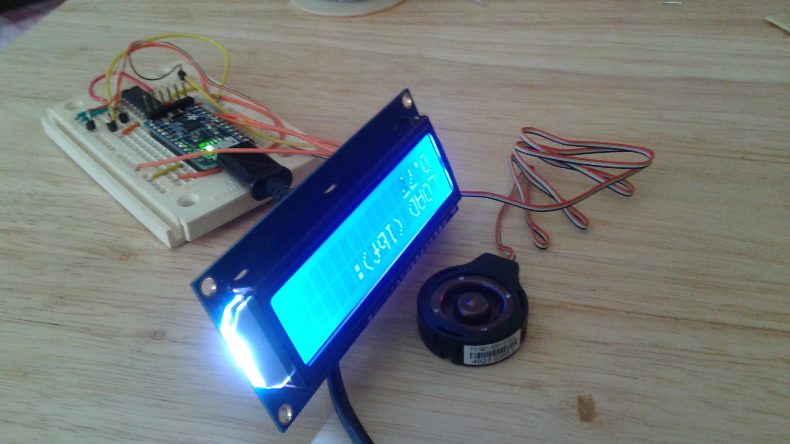
The next step with the electronics is to make a more durable electronics assembly and add the other 3 load cells.
With the electronics progressing, I've also started making the modifications to the test stand to put the load cells where the weight of the quadcopter can rest on them. Below is a picture of the new mounts on the left and the previous mounting on the right. Previously the support lines were attached to two eye bolts. The new method uses a 2x4 block attached with 4 screws on top of the block a recess was cut out for the load cell. A support bar sits on top of the load cell and the support bar has eye-bolts where the support lines are attached. We want the load on the load cells to be purely axial, so a piece of all thread was run across the test stand and the support bar is attached to the all thread with brackets. The brackets and support bar can swivel about the all-thread as one assembly. This makes it so that A) all the weight is supported on the load cells, B) the brackets keep the support bar from moving side to side and C) the ability to rotate about the all-thread eliminates any moments.
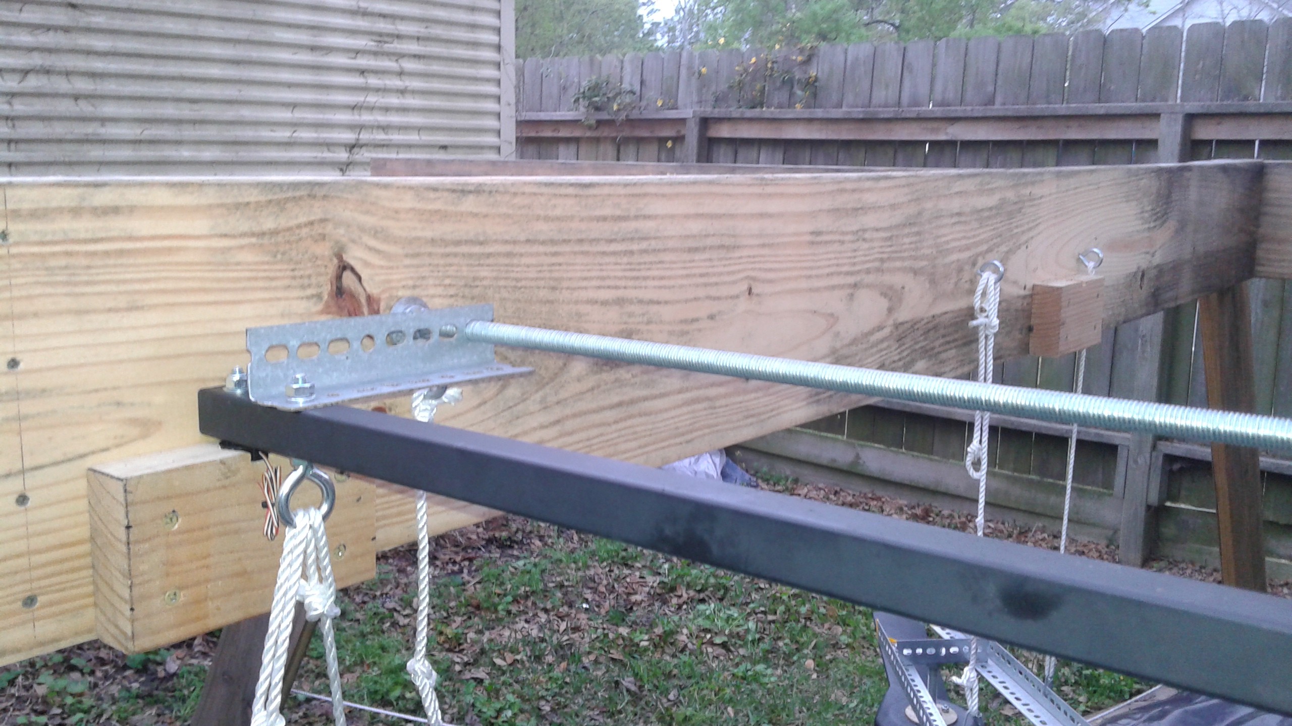
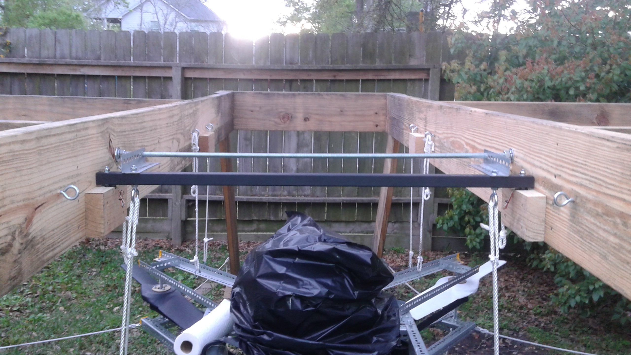
Here is the first support bar installed and the new lines attached.
Here's a picture showing more detail on the load cell blocks. The recess was created by drilling a one inch diameter hole and cutting out the side for the wire.
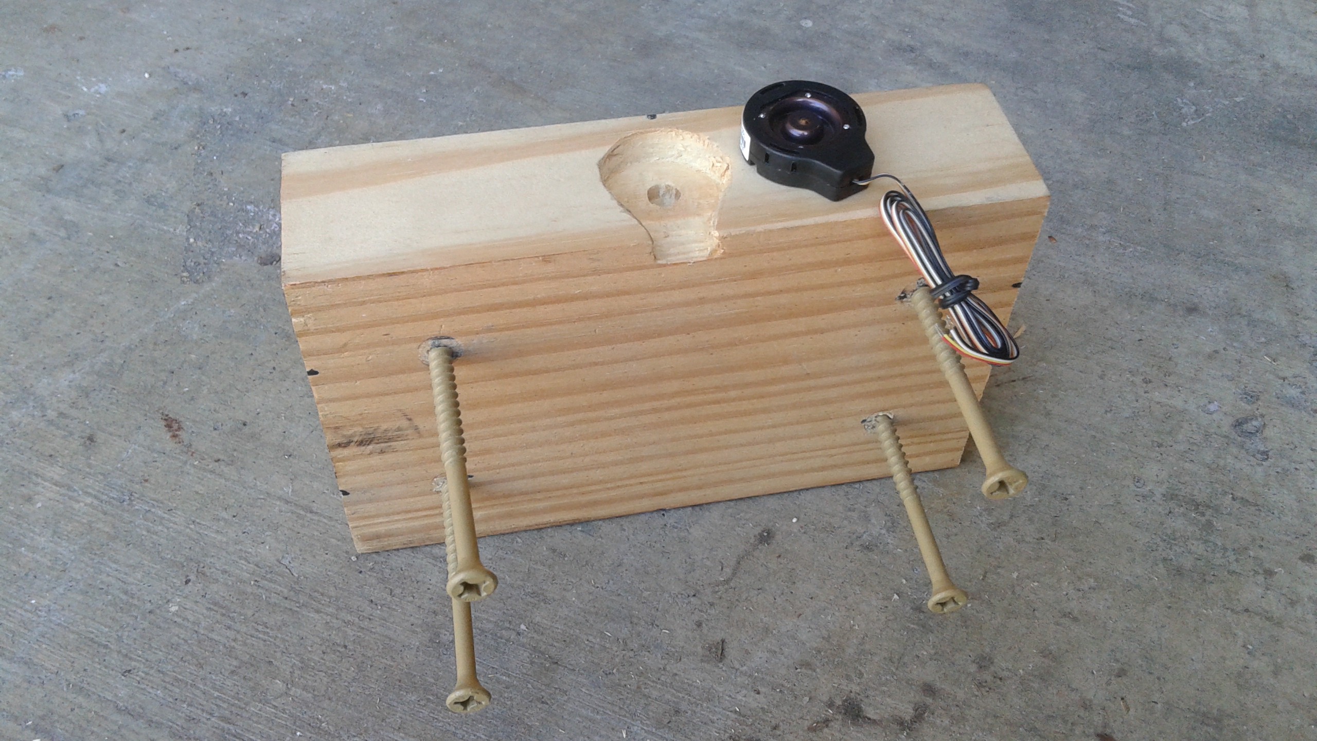
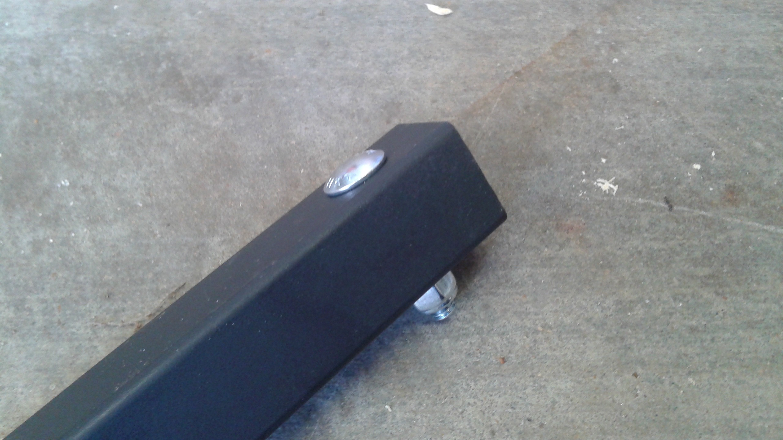
Also to make sure the load sits in the center of the load cell, I placed two 5/16" carriage bolts on the ends. The heads of the carriage bolts are what rest on the load cells.
Before doing the second support bar for the other half of the vehicle or actually connecting the electronics, I decided it would be good to make sure the support bar setup would stay together during testing. Late this evening I ran the test and the new support bar worked perfectly. However the rest of the test didn't go as smoothly. Nothing major, but I'll have the video posted tomorrow to show what happened.
Discussions
Become a Hackaday.io Member
Create an account to leave a comment. Already have an account? Log In.