 Kumar, Abhishek
In this log I explain the BeagleLogic cape schematic.
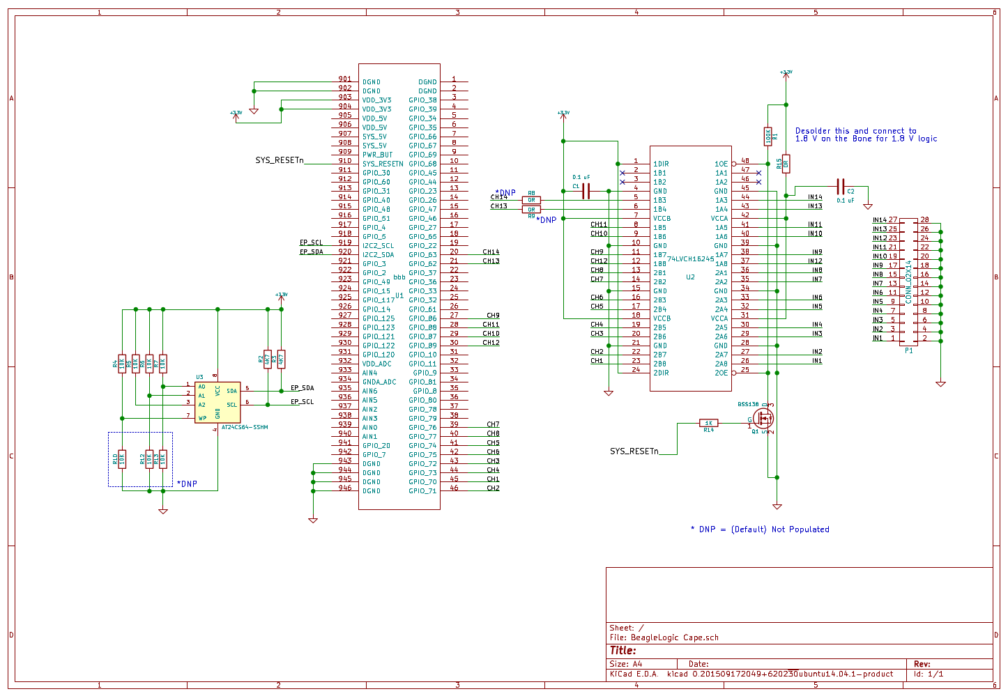
At the heart of the schematic is a 74LVCH16T245 logic level translator IC. This translator inputs are 5V tolerant so it shields (and up to a limited level in case of overvoltage transients) the BeagleBone Black from external circuit logic levels. Therefore with the cape you can debug TTL circuits and Arduino circuits without fear of harming the BeagleBone Black in normal usage.
The inputs of BeagleLogic are also the boot pins for the AM335x and hence must not be changed by external circuitry during the boot phase of the SoC. How do we ensure that external pin disturbances do not cause the BeagleBone to lock up at boot?
The answer is - through the little BSS138 MOSFET connected to the SYS_RESETn pin of the AM335x SoC. This pin is pulled low during the SoC boot and goes high after the SoC has booted up. When the pin is pulled low, the MOSFET is off, hence the OE pin of the 74LVCH16T245 buffer is pulled high by the 100K resistor causing all the outputs of the 74lVCH16T245 (the B rail in this case) to go high-impedance thus not disturbing the logic levels on those pins. Once SYS_RESETn is high, the MOSFET turns on and pulls OE low so that the outputs are enabled and follow the BeagleLogic inputs.
Thus using a cape not only provides a layer of logic translation but also a layer of isolation so that if connected to an external circuit with the BeagleBone powered down, the inputs do not accidentally parasitically power the AM335x SoC.
The EEPROM is there for cape configuration, however may be removed from the next iteration of capes as the BeagleLogic system image handles the configuration automatically.
Discussions
Become a Hackaday.io Member
Create an account to leave a comment. Already have an account? Log In.