Hackaday.io Hackaday.io
Projects
Recently Updated Most Likes Newest Project Lists
Discover Contests Courses Stack
More
Courses Tutorials Events Hackerspaces Profiles Hackaday.com Tindie Marketplace
Sign up Log in
Close
0%
0%

TwinTeeth: The PCB mini-factory

Diyouware TwinTeeth is a open-source PCB mini-factory targeted to the electronic hobbyists.

DiyouwareDiyouware
Following Follow project
Liked Like project

Become a Hackaday.io member

Not a member? You should Sign Up.

Already have an account? Log In.

Sign up with Github
Sign up with Twitter
OR
Forgot your password?

Just one more thing

To make the experience fit your profile, pick a username and tell us what interests you.

Pick an awesome username
hackaday.io/
Your profile's URL: hackaday.io/username. Max 25 alphanumeric characters.
Pick a few interests
Projects that share your interests
People that share your interests

We found and based on your interests.

Choose more interests.

OK, I'm done! Skip
Join this project
Similar projects worth following
6.7k views
2 comments
700 followers
46 likes
  • Description
  • Details
  • Files 0
  • Components 0
  • Logs 7
    • View all
  • Instructions 0
  • Discussion 2
View Gallery
6.7k
2
700
46

Team (1)

  • DiyouwareDiyouware

Join this project's team
  • Diyouware
  • TwinTeeth Video
  • TwinTeeth Building Tutorial
  • TwinTeeth Shop
ongoing project
drill press arduino ROBOT open source manufacturing smt delta pcb delta robot Pick & PLACE PCB LASER printer PCB ETCHING SOLDER PASTE DISPENSER

This project is submitted for

  • Hackaday.com Tip Line

This project was created on 02/22/2015 and last updated 5 years ago.

Description

Diyouware TwinTeeth is a open-source PCB mini-factory targeted to the electronic hobbyists. It is an innovative fabricator of Arduino™ shield-size PCBs which will help you to make PCB prototypes at home.

It includes the following functionality:

- UV Laser photoengraving on sensitive film or presensitized boards using an ultraviolet laser.
- Drilling vias and holes using any mini-rotary tool like Dremel® or Proxxon®.
- Dispensing solder paste with precision on SMD PCB pads.
- Plotting circuits with a permanent pen-maker (if you prefer this method).
- 3D printing knobs, casings, front-panels, even print circuits with conductive filament, or make circuits supports.
- Milling/Carving soft materials or etching PCB copper with a v-bit (if you prefer this etching method).
And much more… because it is extendable and you can use any other tool you can fix on it.

Project Logs
Collapse logs

  • Making PCB vias using conductive ink

    Diyouware • 11/21/2015 at 14:49 • 0 comments

    We developed an alternative method for making PCB vias through-hole.

    There are several commercial products for making DIY PCB vias. Some based on special pins made for this purpose but they are ugly, cost money and difficult to install. Others methods are based on conductive epoxy which also is expensive and resistivity is not good.

    Electroplating is the method used by the PCB industry. There are on the internet some interesting experiences, but all of them require special equipment and unpleasant chemical products difficult to find.

    The traditional DIY method consists in threading a wire through the holes and then soldering it and then cutting it off. For example, if we have 100 vias in our PCB, we have to insert the thin wire on each hole, cut it and solder it 200 times. This is time-consuming, but also tedious, absurd, prone to failures and produces a melancholic state of mind.:-)

    So we decide to innovate in this area developing a new method which consists in drilling blind vias instead of holes and filling them with conductive ink.

    Really we don’t need holes to make vias. Well, we need holes, but not through-holes. I mean, we can avoid drilling to bottom copper layer and make tiny wells instead of vias!

    Then fill the wells injecting the conductive ink. We do it from inside, inserting a needle into the well, mainly because it will be difficult to fill it from outside due to the air inside the well and also surface tension forces.

    Both are simple task for a PCB robot.

    We published all the information in our blog:

    http://www.diyouware.com/node


  • New TwinTeeth Plus

    Diyouware • 11/10/2015 at 17:20 • 0 comments

    We just released a new model: TwinTeeth Plus

    For more information: www.diyouware.com


  • New Improvement

    Diyouware • 09/19/2015 at 13:05 • 0 comments

    We published a lead-screw improvement to the original design. We decided to reduce the size of the acme screws to reduce possible wobble and we also designed a new lead-screw top support which will hold the bearing and a bolt to adjust the motor coupler flexibility.

    You can see the new design here:


    http://www.diyouware.com/node/193

  • The tutorial is ready!

    Diyouware • 06/22/2015 at 11:41 • 0 comments

    We published last chapters of the "How to use it" tutorial.

    You will find them here http://www.diyouware.com/twth_useit in English.

    And here http://www.diyouware.com/es/twth_useit in Spanish.


    The assembling guide is also complete:

    English:

    http://www.diyouware.com/twth_buildit

    Spanish:

    http://www.diyouware.com/es/twth_buildit


  • Twinteeth building tutorial - New chapters published

    Diyouware • 05/13/2015 at 17:54 • 0 comments

    We published new chapters of the TwinTeeth building tutorial:

    Chapter 4 – Wiring the electronics

    Chapter 5 – Installing the Software

    Chapter 6 – Calibrating the robot

    Chapter 7 – Assembling the Laser ToolHead

    Chapter 8 – Assembling the Drilling Toolhead

    Chapter 9 – Assembling the Solder Paste Dispenser Toolhead

    You can find them here in English:

    http://www.diyouware.com/twth_buildit

    and here in Spanish:

    http://www.diyouware.com/es/twth_buildit

    Diyouware Team


  • New Toolhead

    Diyouware • 04/10/2015 at 12:18 • 0 comments

    We designed a new ToolHead: the microscope ToolHead.

    You can take a look it here.

    We also published more chapters in the tutorial.

  • Twinteeth building tutorial - Chapter 3 published

    Diyouware • 03/18/2015 at 10:08 • 0 comments

    We have just published a new chapter of the TwinTeeth building tutorial.

    You can find it here in English:

    http://www.diyouware.com/twth_buildit

    and here in Spanish:

    http://www.diyouware.com/es/twth_buildit

    Our plan is to write and publish a chapter every week.

    We will keep you informed.

    Diyouware team.

View all 7 project logs

Enjoy this project?

Share

Discussions

Log In/Sign up to comment

Become a Hackaday.io Member

Create an account to leave a comment. Already have an account? Log In.

Sign up with Github
Sign up with Twitter
OR
Diyouware wrote 03/26/2015 at 16:54 • point

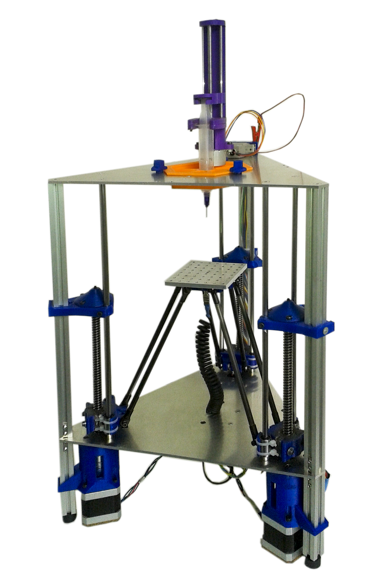
Mainly because in that configuration the laser beam is not attached directly to the motion system. We already tested a traditional cartensian robot and we could not avoid vibrations and resonances produced by the mechanics and the belts. Also the inverted delta configuration allows us to change the tool in a question of seconds. This is very important in a multi-functional robot. We don't care too much about the Z axis lenght because the robot was mainly designed to process PCBs and 3D print small things.

  Are you sure? yes | no

suicidal.banana wrote 03/25/2015 at 15:09 • point

Love it! 

Just wondering why you went for a delta approach (creating a quite tall machine) when all you really need here is X & Y? (ok ok, and rougly 2-3cm of Z) just for the fancy ascetics/because you can? or is there an idea behind it?

  Are you sure? yes | no

Similar Projects

Hackaday Prize 2019
The thinnest Magnetic Actuator!
Project Owner Contributor

Flexible PCB Actuator

Carl BugejaCarl Bugeja

A full-on informational review about all aspects of PCBWay's PCB prototype service, with my own opinion and experience of their service.
Project Owner Contributor

My Full Review and Experience with PCBWay

ElectorialsElectorials

The very first prototype PCB testing the new pcb-rnd->FidoCadJ->pcb-rnd toolchain easing freeform bezier & cubic spline track/PCB creation.
Project Owner Contributor

Noo-D(l)eus Ex Machina - Freeform PCB design proto

a1039181a1039181

Official Hackaday Prize Entry
Open layout for modular prototyping with attiny 24/44/84's and 25/45/85's
Project Owner Contributor

Attino

Non-ICENon-ICE

Does this project spark your interest?

Become a member to follow this project and never miss any updates

Going up?

About Us Contact Hackaday.io Give Feedback Terms of Use Privacy Policy Hackaday API

© 2021 Hackaday

Yes, delete it Cancel

Report project as inappropriate

You are about to report the project "TwinTeeth: The PCB mini-factory", please tell us the reason.

Send message

Your application has been submitted.

Remove Member

Are you sure you want to remove yourself as a member for this project?

Project owner will be notified upon removal.