 arko
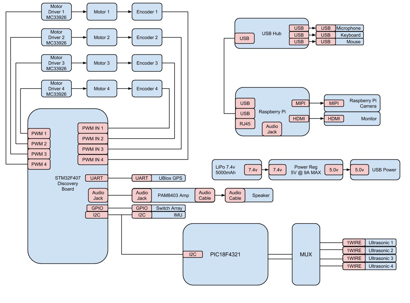
arkoShown below is our schematic. The STM32 is responsible for driving the motors, reading their encoder feedback, querying the GPS and IMU, driving the speaker (signal), listening for the go switch, and communicating with the PIC18F4321 which is responsible for processing the sonar data. All power is 5V and VCC is 3V. We originally planned to implement a Raspberry Pi 2 as our computer and use the OpenCV libraries for vision processing, however, due to time constraints we had to abandon task. Our system is entirely based on IMU and sonar for sensing, and the motor control/encoders for driving and feedback.
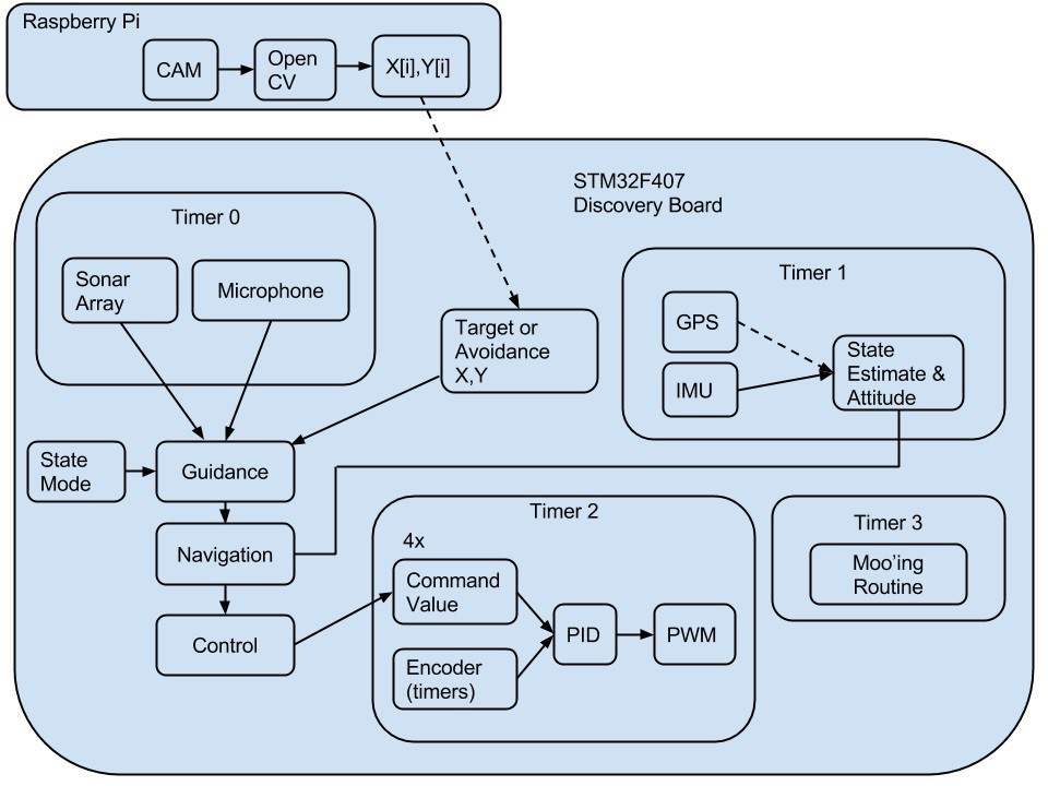
System Overview:
Our system design, as shown below consists of 4 essential processes. The first is a routine which queries all sensors, sonar, microphone, IMU (inertial measurement unit), and GPS. Using the following data, and based on the specified state mode, the second route, the robots guidance state machine, decides an action and executes it. If an obstacle or disturbance is introduced into the system, the robots halts the process and decides the appropriate contingency plan to execute. The third routine is the time sensitive control systems code which is responsible for odometry and keeping the motors at a target commanded value. The final routine is responsible for any low priority (yet important) tasks such as "mooing" the speaker.
Software Overview:
Having purchased appropriate DC motors, wheel hubs, tires, and a chassis, the next step in building our system was to develop an intelligent way of controlling the motors. From a high level point of view, it would be nice if we could simply think (programmatically, as robots do) about going straight at a certain speed or turning about a certain radius and having it happen. Our ability to reliably and efficiently carry out these "low level" tasks is pivotal; the entirety of our task-completing ability depends on this movement. It cannot be over-stressed how important a solid control system overlaying the DC-motor-controlled wheels is.
The first step here was to read our encoder values. This is done directly on the STM32, where we use timers and interrupts to determine the four frequencies. We only have one encoder returning from each wheel, which gives us the speed of the wheel; direction is determined from the current settings of our motor driver, which determines direction. Then we were able to advance to open- and closed-loop control of the wheels. Our command for each wheel is given as frequency, the desired frequency of the encoder feedback. Below is a simple block diagram of our closed-loop control.

Next we added our PID controller. Tuning each wheel became necessary, as no set behaved similarly enough to tune together. The good news, however, is that once PID tuning is completed, high-level programs can utilize the PID controller simply and easily. The tuning process was methodic and repeatable, which was good because we needed to re-tune a couple of times over the course of lab. The process is such: Having basic PID control code initialized, we set the integral and derivative terms to zero while tweaking our proportional term (KP). A good value is found by feel more than anything else; we could hear the motors respond and see (via live debugging) the current encoder frequencies. Next, keeping KP the same, we do the same with the integral term (KI), and finally with the derivative term (KD). Some slight changes to KP are made along the way to ensure a more ideal response, also. Each wheel set came out with its own gain values, with which our vehicle responded well.
We must note here that our PID tuning takes place on a stand, where the wheels are free to spin unloaded by the weight of the vehicle and with the friction of the ground. For the most part, the difference between unloaded and loaded operation did not seem to affect our tuned system. However, our back-left wheel did react noticeably slower when loaded. It did not take much more guess-and-test tuning to mitigate this to manageable levels, fortunately.
Here, we could talk about using each wheel's open-loop step response to build models for them, allowing us to model the system as a whole and compare experimental and theoretical tuning values and various responses; however, we felt that we have plenty of other work to do towards completing a functional 'bot, and that the process would not help much in that regard, seeing as we already had a working, tuned system.
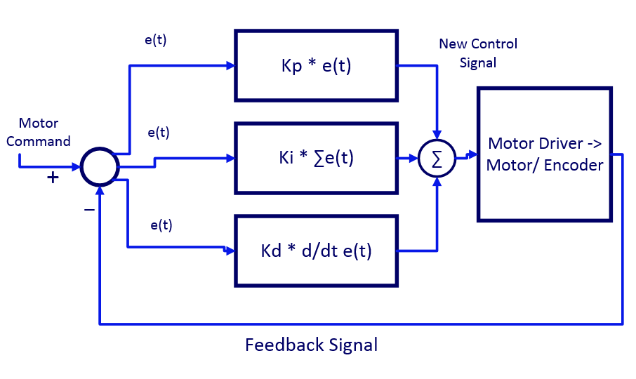 Above is our final, closed-loop system in block diagram form.
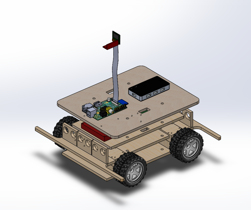
We chose the layout of the hardware with the intention of keeping all the components spaced out for a clean orderly design. The layout started its life with a rough idea of where we wanted the components to be located. Precision came with the use of Solidworks. Each component of the robot was measured and represented with block models took up the volume of space required and the component hole positions. With the layout made in the 3D model, we were able create new platforms that would suit our needs.
The robot is broken up into 4 levels using a modified version of the Boskovich stock robot. The levels are internally labeled as levels 1 - 4 with level one being the lowest level and 4 as the top level. Level one is dedicated to the power supply utilizing the stock spacers. This level required dual spacers to fit the lithium polymer battery.
Level two is designated the power management level with the power distribution rail, 5V regulator and the required wiring to distribute power as necessary. Only a single spacer was required here so that we can save space for the much larger and taller STM 32 and 32 breakout board.
Level three is designated for the STM and the motor drivers. This level required 3 spacers to clear all the wires and the height of the breakout board, the wires and the wire ends. Level three is the obvious choice for these two components as the wires from the main power rail will only need to traverse a single level to reach the motor drivers, which at this level can will have the shortest required wire length to reach the motors.
Level four is our sensor processing level. This level houses the sonar sensors, the sonar processing microcontroller, and the Raspberry Pi 2 used as the vision processor. The IMU is mounted solidly on this level, with rubber grommets to shield it from vibrations. This level is the top level and as such will be closest to the sensors but still only a single level away from the STM32. The sonar sensors are placed on the same level as the sonar processors.
Levels three and four were rebuilt with new platforms cut to our specifications. We used an available laser cutter to cut our new platforms out of MDF. This material was chosen for its adequate strength, relative light weight and ease of manipulation. The ease of manipulation was an important aspect of the material because we would need to make many adjustments and extra holes. Preliminary holes were made using the CAD file and the laser cutter for the major parts. For these two levels we also made wiring pass through to keep all wires that would traverse between levels inbound such that there would be no interference with the wires and the moving parts.