 j0z0r pwn4tr0n
The first step of a big project like this is doing the research to see what work has already been done and what needs to be done. In reviewing the information provided on the websites in the description, I think I have found all I need to make this work with a few modifications.
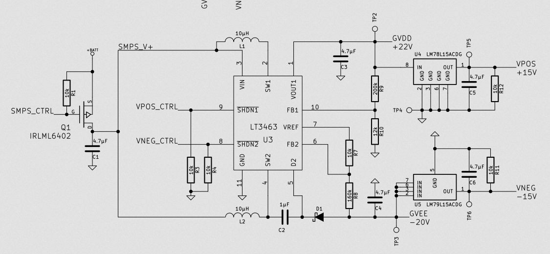
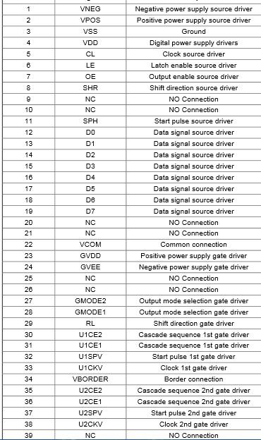
Petteri Aimonen of the website essentialscrap.com has put together a pretty in-depth look at the ED060SC4 screen and how to drive it. His website has numerous links to datasheets and brochures on e-ink displays as well as diagrams showing the pitfalls he has encountered in making this display function for his needs. His project drives the screen with an STM32 programmed in C. He also has an excellent schematic which uses Texas Instruments op-amps to supply the necessary positive and negative voltages.
This is an excerpt from his schematic, I'm going to use this part for the voltage generation:
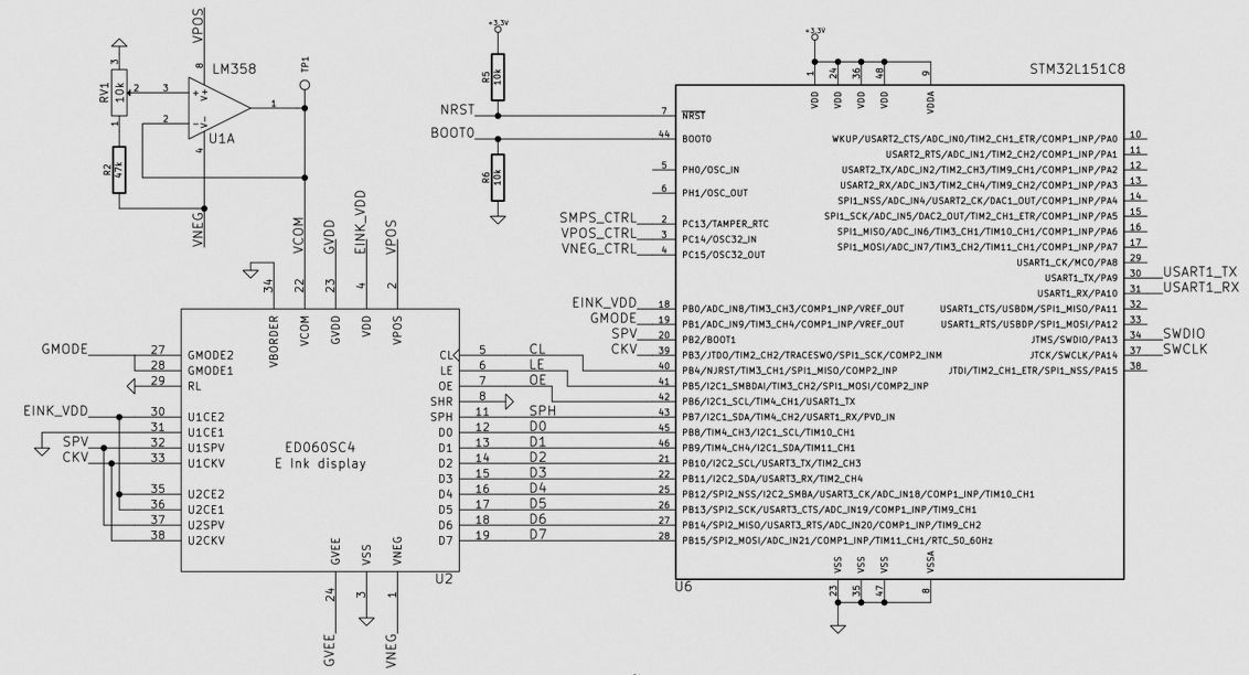
 I should be able to use that part without any major modifications. The other part drives the screen with the micro controller:
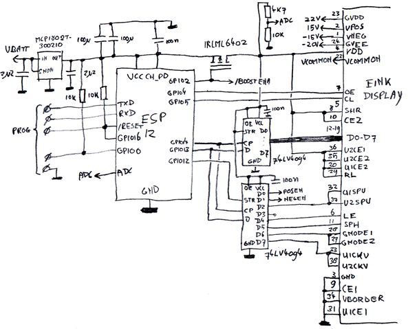
SpriteTM has a similar project, using an ED060SC4 paired with a ESP8266 to make a wifi-enabled whiteboard. There are a few significant differences between his version and Petteri's, the biggest being that he uses a shift register to clock the data in since the ESP8266 doesn't have very many exposed GPIO to work with. Here's the relevant portion of his schematic:
After that, I need code to get my pixels onto the screen. Petteri Aimonen has posted his C code on github, and I'm hoping that I can just change his pin definitions to the GPIO used on the Raspberry Pi and it will just work, but let's face it; it won't be that easy.
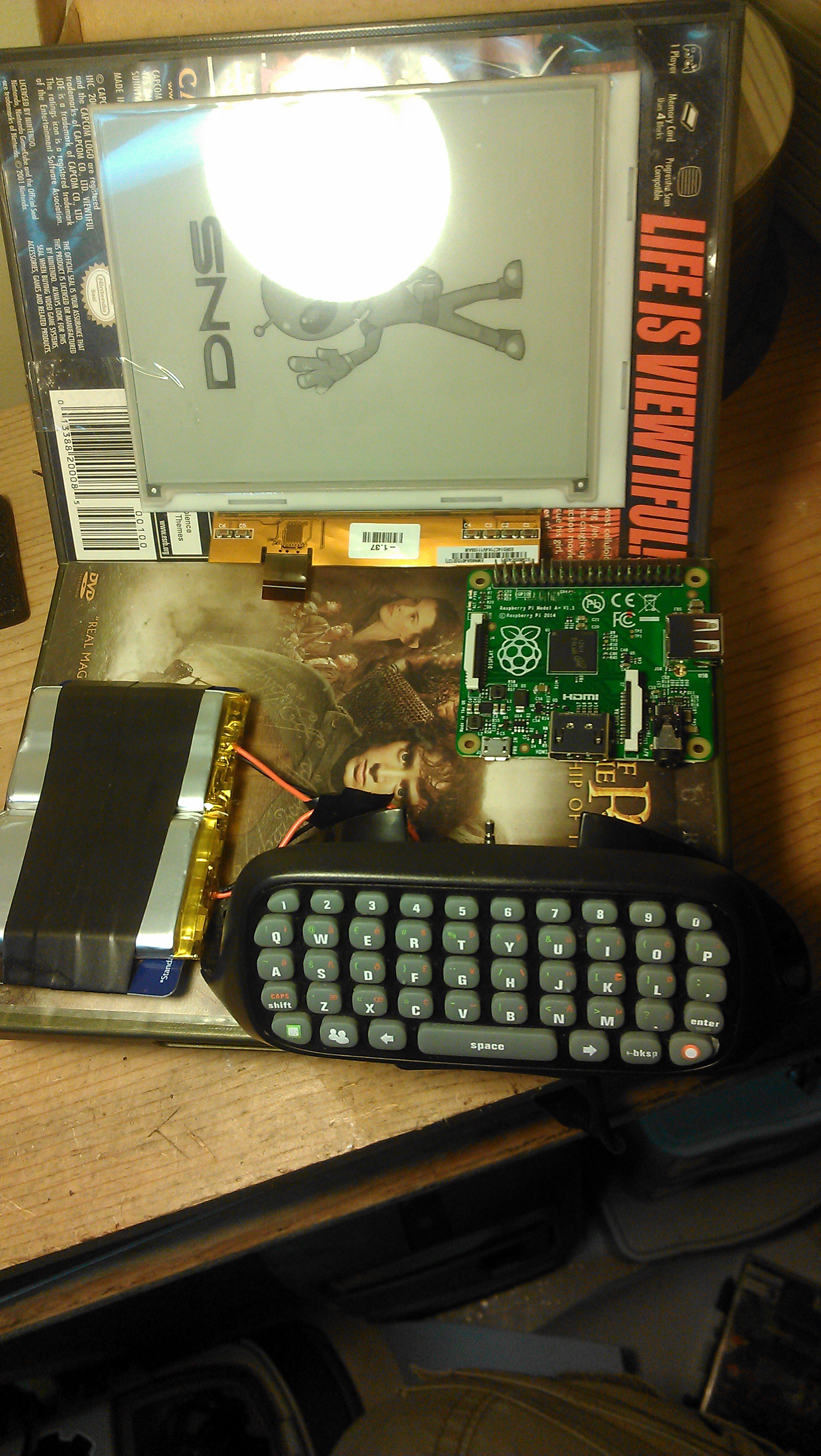
While I was doing research, I was also playing with some of the components to get an idea of the layout. For some reason, the final layout drives my design decisions so it's one of the first things I envision. Also this is the first Raspberry Pi A board I have owned, and they are so small and cute!!!
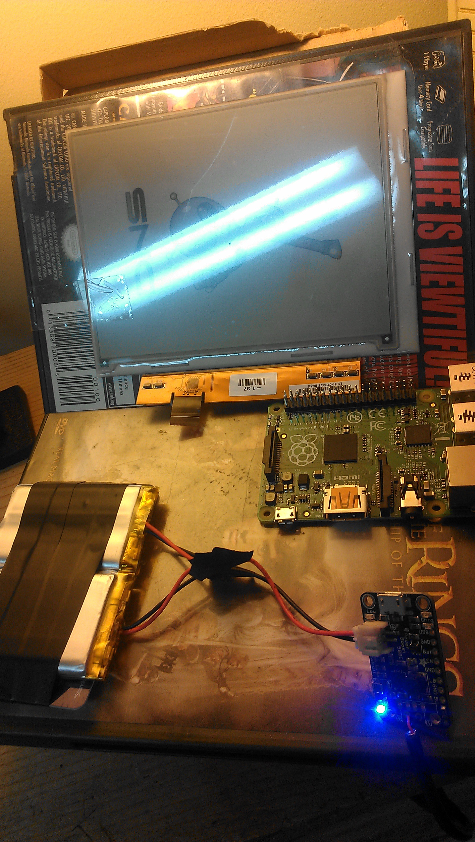
One last tidbit for this update: Power!!! Some back-of-the-napkin calculations tell me that this contraption should pull about 250 mA per hour, and even this only if the screen was constantly updating. If these calculations are correct, I should be able to get 20 hours of operation from my 5000 mAh battery pack that's pictured above. This is also good because the solar panel I'm eying supplies about 330 mA per hour, which means I could charge it and use it at the same time.
That's all for now, thanks for all the follows and skulls!!! It's great motivation to keep me working. My next step will be to replicate the schematic and make the e-ink display something.
Discussions
Become a Hackaday.io Member
Create an account to leave a comment. Already have an account? Log In.