0%
0%
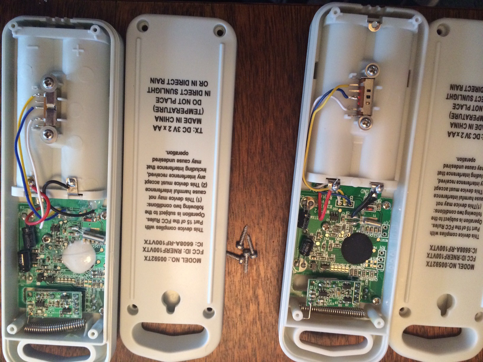
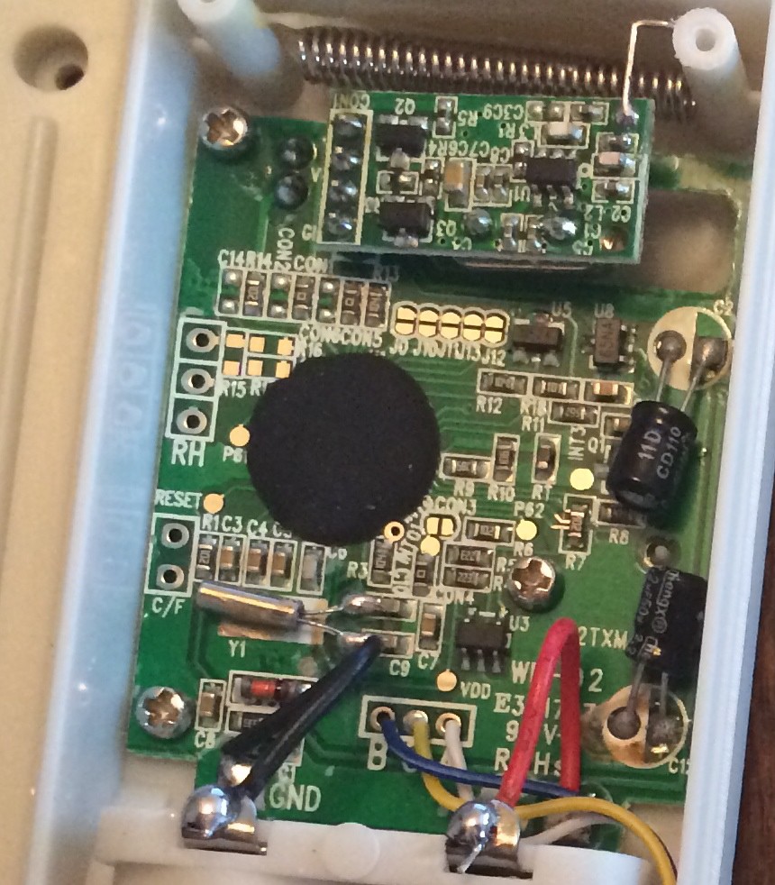
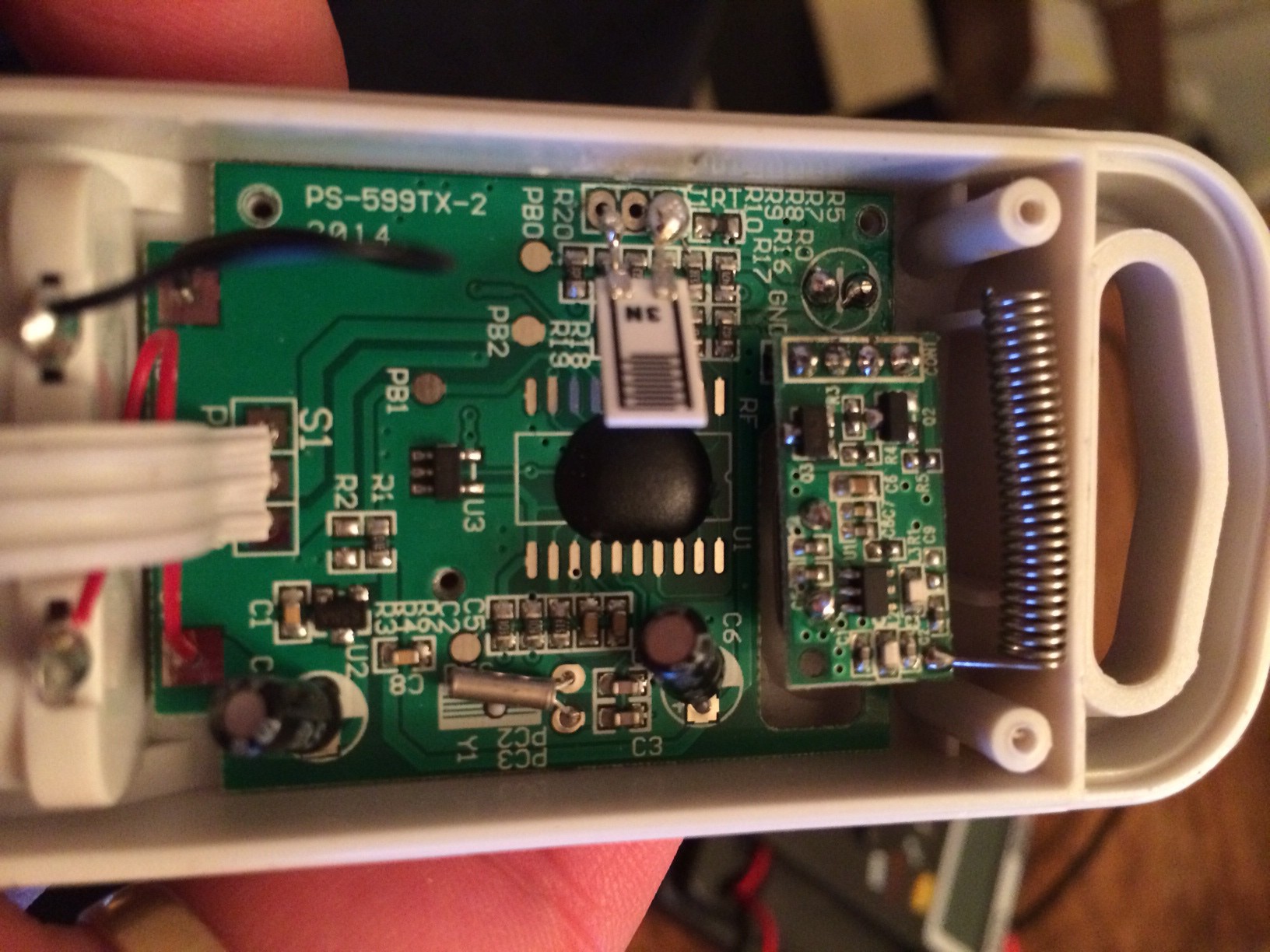
re-purposing acurite temperature sensors
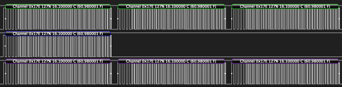
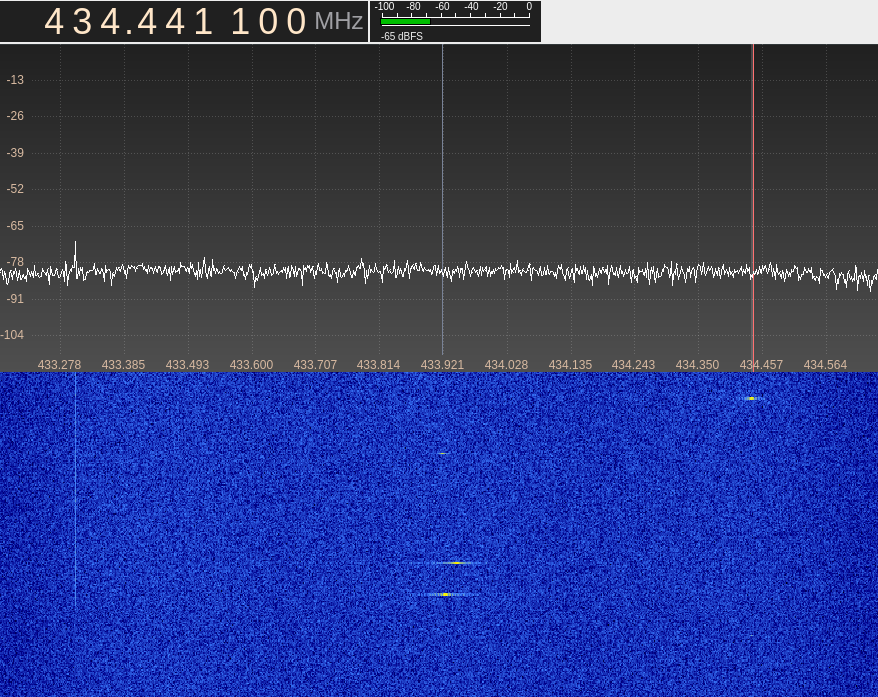
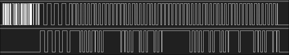
Two people have reverse engineered most of the protocol. These things are cheap, and do something I wanted to build. Time to finish the job.
 Jorj Bauer
Become a Hackaday.io member
Already have an account? Log in.
Just one more thing
To make the experience fit your profile, pick a username and tell us what interests you.
Pick an awesome username
hackaday.io/
Your profile's URL: hackaday.io/username. Max 25 alphanumeric characters.
Pick a few interests
Projects that share your interests
People that share your interests


 staticdet5
 Tim Rightnour
 Alex
Alex
 Joel Murphy
Just found this project. It was Accurite that drove me to do this project: https://drgerg.com/pinet-the-weather-station.html . It was fun on the front-end, and is still out there years later, doing its thing.