 Jorj Bauer
Next: I hate hacking up the original receivers for these kinds of projects. I could rip the (211AYQS) receiver out of the "inside" unit, harness that on a microcontroller, and be done. But no; just like I never ripped the WWVB receiver out of the "atomic" clock - which I bought for the express purpose of ripping the WWVB receiver out of it, sigh - I know I'll never be satisfied ripping the receiver out of this AccuRite thing.
So my plan is to use an RFM12B, instead.
I've now got it receiving a reasonable facsimile of the transmitted signal. (Comparing the received signal from the 211AYQS receiver and the bitstream coming out of the RFM12B using a Saleae Logic shows they're pretty close.) It took some work to get here.
First: the RFM12B had to be hacked to work in OOK mode. (By default, one of the caps on the board defeats the fast voltage swings needed for OOK.) On the third try, I settled on a 150pF capacitor, replacing the 4.7nF capacitor next to the IC (a 100pF cap seemed too small; 220pF didn't seem to help any either; and in retrospect, they were all probably fine). This is all as-documented here: [OOK ASK with a modified RFM12B]
Second: the Jeelib code for OOK mode needs to be tweaked. Specifically, the initialization sequence (starting with the RFM12B_OOK example project) needs to be changed to better support the temperature sensor protocol, specifically on the four lines that I comment here:
rf12_control(0x8017); // 433 MHz; not 868 MHz
rf12_control(0x82c0);
rf12_control(0xa68a); // technically, 0xa620 would be the center frequency, but this works as-was
rf12_control(0xc655); // Set baud rate to 4k, not 4.8k
rf12_control(0x948a); // Raise DRSSI limit to -91dbm from -97dbm
rf12_control(0xc220);
rf12_control(0xca00);
rf12_control(0xc473);
rf12_control(0xcc67);
rf12_control(0xb800);
rf12_control(0xc800);
rf12_control(0xc040);
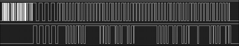
Without these changes, the data doesn't come out of the RFM12B cleanly, as seen in this image (top is the data as received by the 211AYQS; bottom is as received from the RFM12B):
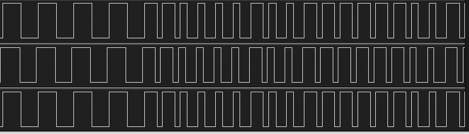
Once it's properly tuned, the data is much more reasonable (top and bottom traces are both the RFM12B, being tested from two different points on the board; the center trace is the 211AYQS, which seems to receive the data just a smidge faster):
And that's as far as I've gotten. Next up, I have to write a new demodulator...
Discussions
Become a Hackaday.io Member
Create an account to leave a comment. Already have an account? Log In.