Close
0%
0%

DerbyLink USB to RS232 over CAT5

USB to RS232 converter using RS422 over CAT5 as an intermediary. For my youngest son's Cub Scout pack to simplify Pinewood Derby wiring

Similar projects worth following
I'm the Pinewood Master for my youngest son's Cub Scout pack. Our setup is pretty typical: a 32 foot long 4-lane wooden track, a timing system comprised of a laser gate and a finish line, and a PC running race management software. What's always been a pain the butt is all of the cabling required. A 9V wall wart for the finish line. An RS232 cable from finish line to PC. A wire between laser start gate and finish line. The RS232-to-USB dongle. Of main concern are the wires running to/from the finish line, as that is where the excited scouts (and parents) tend to congregate during the race. Particularly the 9V wall wart and AC cord near the finish line. It's a trip hazard.
This project is an attempt to alleviate the wiring mess. Two metal boxes, and a length of CAT5 cable in between. The cable carries the serial data between PC and the finish line, as well as power for the finish line. Getting the wiring more organized should be a big help!

This project has been on the drawing board for a couple of years now. It gets pushed back up to the top of the list towards the end of each calendar year, with the Cub Scout pinewood derby each January serving as the reminder. Next year will be my last year with the Cub Scouts (my youngest son moves on to Boy Scouts next year) so 2016 will be my "swan song" in terms of the pinewood derby. So, it's now or never! (well, not really, but I'll use that as motivation)

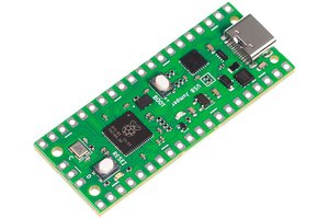
I opted to use a few "off the shelf" items rather than a complete "from scratch" design. I have a bunch of DLP designs' DLP2232 USB to UART bridge modules laying around, so I used one of those. I purchased several LM2596HV DC-DC modules a while ago, so rather than rolling my own (or copying that one) I just place the whole PCB module onto the board. Sheer laziness on my part.

The PC-side box is the easiest to describe, so I'll start there first. This is really just a USB-to-RS422 converter. I had several MAX485 RS485 transceivers laying around, so I use two of those, each one permanently fixed as either an RS422 transmitter or a receiver. The MAX485 devices are powered from the USB 5V supply. I use CAT5 pairs 1-2 and 3-6 for the RS422 transmit and receive pair, respectively. I use CAT5 pairs 4-5 and 7-8 for +48V and ground, respectively. This is (intended) to be compatible with how PoE uses a CAT5 cable for power distribution. Of course, I have to have LED's! So, an LED for the USB RX and USB TX activity, as well as an LED for USB 5V, and an LED for 48V. For the 48V indicator LED I decided to implement a voltage detector circuit, that will illuminate the LED only if the applied voltage is above 40V. The intent here is that I don't want this LED to illuminate (even dimly) if a lower voltage is applied - that would lead to more current through the CAT5, which we want to avoid. The idea is, if the 48V LED is on, then everything is OK from the supply side.

The Track-side box is a bit more complicated, but still pretty simple. This is just a RS422 to RS232 converter. Again, I use a pair of MAX485 transceivers for RS422 to logic conversion. I use a MAX232 (OMG I still have tons of these) to convert the logic to RS232 levels, which is what the derby finish line wants. On the track-side, the power situation is quite different. The incoming 48V is bucked down to 9V using a DC-DC converter module from eBay. These modules are cheaper (shipped) than what I would pay to buy the components! A 78L05 linear vreg supplies 5V to the MAX485 and MAX232 devices, and is powered from the 9V output of the DC-DC converter. There are LED's on this side too, naturally. RS232 TX and RX and 5V and 9V indicators. A voltage detector circuit, similar to that on the PC side, only illuminates a 9V indicator LED if the 9V rail is above 8.5 volts or so.

The derby finish line consumes 9V at 600mA, or 5.4W. My measurements while it's operating are quite a bit lower (more like 450mA or so) but I'll use 600mA as a maximum. The DC-DC converter is probably about 85% efficient (ballpark) in this configuration so that's 6.3W required at its input. The result is that about 130mA of current flows through the CAT5 feed, which should be fine - that's well below what PoE applications push through a CAT5 cable.

  • 1 × DLP2232 USB to UART bridge module in 40-pin DIP
  • 4 × MAX485 Switches and Multiplexers / Analog Switches and Multiplexers
  • 1 × LM2596HV DC-DC module from eBay, the 60V to 9V buck converter
  • 2 × LM2904 (LM358) Dual op-amp, used for voltage detectors
  • 1 × MAX232 logic-to-RS232 level converter

View all 6 components

  • Victory!

    tomcircuit02/04/2016 at 03:30 0 comments

    The DerbyLink system was put to the test last weekend - powering the Micro Wizard finish gate, converting RS-232 to RS-422, then RS-422 to USB, and simplifying the wiring down to a single lowly CAT5 cable. A complete success and nothing out of the ordinary to report during the pinewood derby of Cub Scout Pack 45 of Farmington, Michigan. I really like the whole PoE power setup, and I think I'll use it again in any projects that require cabling and power and perhaps not being convenient to an AC outlet.

  • Finishing Touches

    tomcircuit04/26/2015 at 19:08 0 comments

    I whipped up some end panels using Inkscape and sent off to Ponoko for fab. I chose 1.5mm thick black acrylic. Black wasn't my first choice, but Ponoko didn't have many options in acrylic less than 3mm thick. The nice, cheap, extruded enclosures from Adafruit didn't come with dimensioned drawings, so it was a bit of guesswork to get the panel overall size and mounting features, but after a few iterations with paper printouts, I managed.

    I used crayon as the infill on the panels to allow the engraved text to show up. My teenaged son referred to it as "ghetto". I call it "industrious".

    Now, just need to wait until next January to unveil the DerbyLink to the "pit crew"...

  • System test complete

    tomcircuit03/20/2015 at 00:43 0 comments

    I was able to put together an ugly cable between the DB15 and the DC barrel connector and the DB9 serial con on the finish gate. Success! I can power the finish gate through 100 feet of CAT5 cable and the communication is working just fine between the PC and the finish gate.

    All that's left to do now is to draw up some end panels with cutouts and fab those - ponoko maybe?

    Then, all I have to do is wait for next January! :-)

  • Assembled and Testing

    tomcircuit03/17/2015 at 03:48 0 comments

    I finally received my PCB's today. The DirtyPCB service thoughtfully bundled all three board types I ordered (two for this project, one for the Rubidium Oscillator controller project). The board quality seems good. A slight registration error in the silkscreen on one of the boards, but really nothing worth complaining about. It's been a while since I've assembled HASL'd boards - I got spoiled by the ENIG finish that OSHpark provides.

    I put together both boards in less than an hour, and other than having to diddle a resistor value in each of the 48V and 9V voltage comparator circuits, no issues. I think I simulated the comparator circuit with an incorrect value of reference voltage (derived from the 5V power LED) so I had to adjust the divider input R to achieve the correct threshold voltages (40V and 8V). I'll have to look into this to be sure.

    I threw together a quick loopback test setup with the two DerbyLink boards, a 100-foot CAT5 patch cord, a 48V supply, and a 30-ohm load (300mA at 9V) to simulate the draw of the MicroWizard finish line. It's presently undergoing 'burn-in' in my basement lab. I found a nice COM port loopback test program, so I'll let that run overnight checking the USB -> RS422 -> RS232 -> RS232 -> RS422 -> USB link at bitrates between 2400...115200 bps.

  • DerbyLink Proto1 fileset

    tomcircuit03/03/2015 at 02:37 0 comments

    The complete fileset for proto1 of DerbyLink can be found on GitHub
    https://github.com/tomcircuit/derbylink

    Note: not tested yet!

  • Waiting on my dirty boards!

    tomcircuit03/02/2015 at 15:14 0 comments

    I've completed the schematic capture and PCB layout for both sides of the link. I submitted them via the dirtypcbs.com service last week, and waiting on them to arrive. There's a bit of a delay because of Chinese New Year. No hurry, I've got until January 2016 :-)

View all 6 project logs

Enjoy this project?

Share

Discussions

Similar Projects

Does this project spark your interest?

Become a member to follow this project and never miss any updates