Krzysiek
-
External memory pinout
03/15/2015 at 20:13 • 0 commentsWeloop tommy has an external FLASH and RAM. According to product specification it's 16kB RAM and 512kB FLASH.
RAM pinout
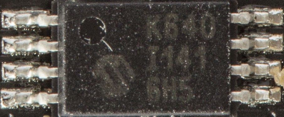
It's easier to describe pinout than indicate a specific chip that's used. RAM looks like a microchip 23K640. Pinout is correct but available size is lower than expected. But that may be an error in specification. It looks like internal RAM size and external RAM size were swapped. Documentation for microchip 23K640 can be found HERE.
![]()
Chip pinout:
RAM pin NRF WLCSP pin NRF pin name SCK J6 P0.11 SI J5 P0.12 SO J7 P0.09 CS B6 P0.23 FLASH pinout
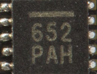
It's even harder to indicate flash chip model. If you know what chip it is please add a comment or write a message.
Update:
It's W25Q40CL. Documentation can be found HERE.![]()
Chip pinout:
FLASH pin NRF WLCSP pin NRF pin name SCK J6 P0.11 SI J5 P0.12 SO J7 P0.09 CS J8 P0.08 WP H6 P0.10 -
Vibration motor and screen backlight pinout
03/15/2015 at 18:29 • 0 commentsNRF WLCSP pin NRF pin name Screen backlight H7 P0.07 Vibration motor C7 P0.29 -
Accelerometer pinout
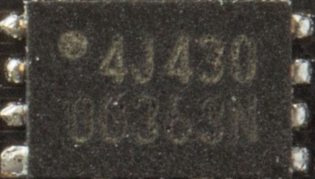
03/15/2015 at 18:20 • 0 commentsIt looks like weloop tommy uses MMA8652 accelerometer. A full documentation and I2C interface can be found HERE.
![]()
Communication is based on I2C interface (SDA and SCL pins) and two interrupt pins.
MMA8652 pin NRF WLCSP ball NRF pin name SCL C9 P0.00 SDA E9 P0.01 INT1 F9 P0.03 INT2 D9 P0.02 -
Watch buttons pinout
03/08/2015 at 20:14 • 0 commentsWeloop tommy has only 4 buttons. Pinout is as follows:
Button NRF WLCSP Ball NRF name BACK G2 P0.17 UP G1 P0.20 SELECT H1 P0.18 DOWN F2 P0.19 -
LCD pinout
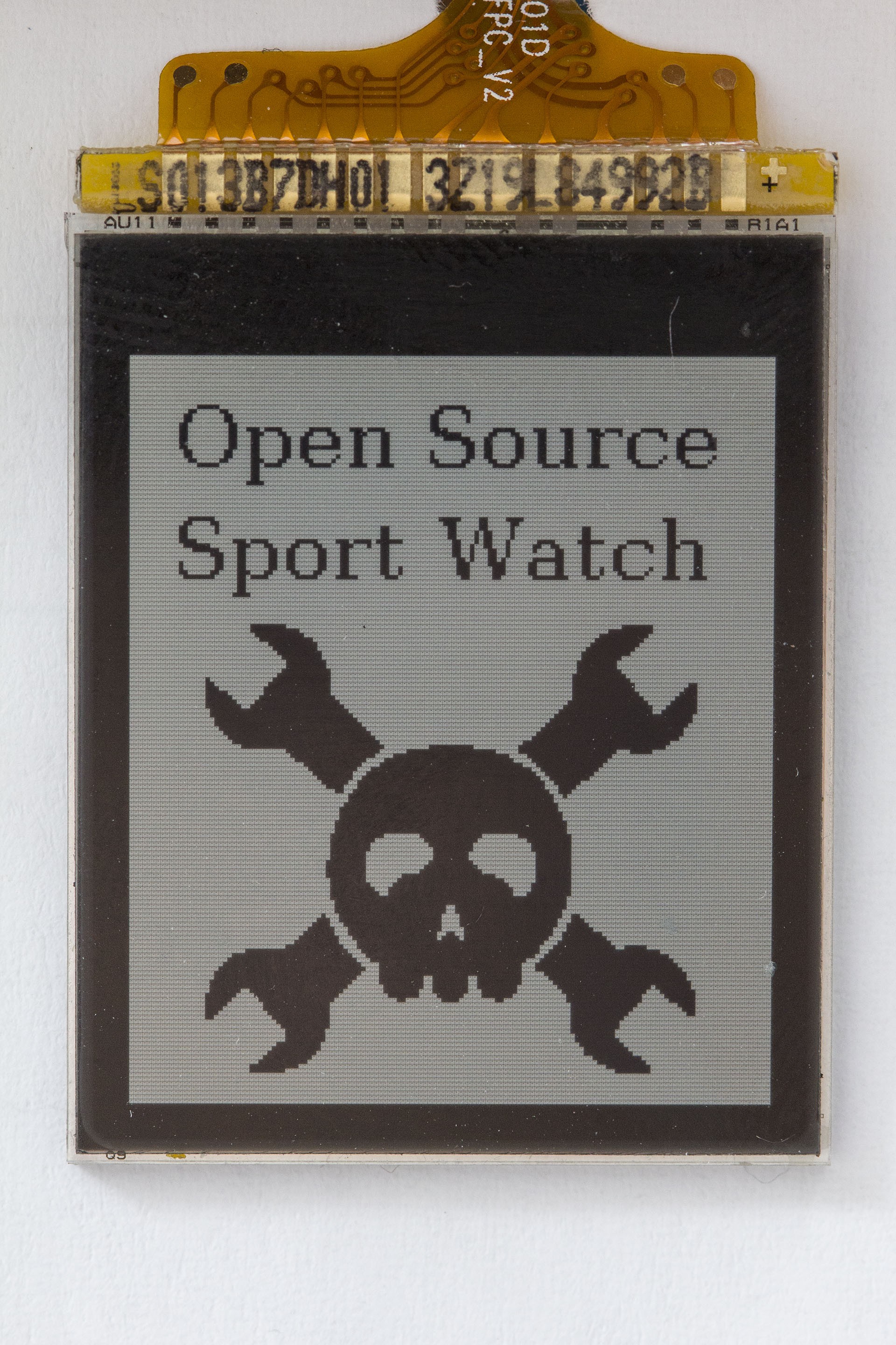
03/07/2015 at 13:38 • 1 commentToday I had some time to check LCD pinout and write a simple app that test weloop tommy LCD.
First thing first, you should read documentation for Sharp memory lcd LS013B7DH01. Next step is to read Programming memory LCD application note so you will know how to communicate with the screen.Communication is really easy, it consists of:
- write only SPI line: SCLK, SI
- chip selection pin: SCS
- screen enable pin: DISP
The only problem with this is to know watch pinout. It's as follows:
LCD Pin SPI name NRF WLCSP ball NRF Name SCLK SCLK E8 P0.31 SI MOSI B7 P0.28 SCS SS D8 P0.30 EXTCOMIN - F8 P0.04 DISP - G8 P0.06 EXTCOMIN pin can be skipped because EXTMODE pin is grounded on board.
SPI MISO line is not used so can be set as NC in code.
This LCD requires 5V power supply, by default 5V voltage regulator is disconnected so LCD does not work, use P0.13 to enable voltage regulator!
The most important SPI commands are
- override single line
- override multiple lines
- clear whole screen
You cannot change just one pixel, the smallest accepted data portion is one line. Full description of a command structure and list of all commands can be found in Programming memory LCD application note
I've created a simple app that shows how to communicate with screen. It can be imported and compiled on mbed site.
![]()
In a few days I will publish pinout for:
- watch buttons
- backlight
- vibration motor
To write an accelerometer demo I still need a new watch. Thank you all for the donations, $30 more and I will have it. If you want to help please donate HERE. Thanks!
Open source sport/smart watch
Make Weloop Tommy an open source sport watch that can connect directly to all kind of sensors (heart rate monitor and so on)