 Ahmed Hefnawi (Volta)
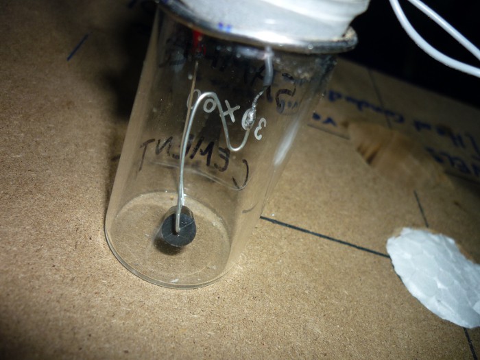
It's time for calibrating the calorimeter! There are two parameters I'm interested in for the cement hydration process, which are:
- Calibration Coefficient
- Baseline
Calibration Process
- Measuring The Calibration Coefficient
- I'm using the following items
- A pair of 1/4W and 0.1% accuracy 120Ω precision resistors, they will act as the heaters during the calibration process. One is placed inside the sample vial and the other is an external resistor placed in series with the one inside the vial to be able to measure the current going through the resistor (to eliminate errors from resistor leads).
- An external power supply to go through the resistors is a 12V DC coming from an ATX computer power supply or a 9V DC battery.
- A Multimeter to measure the voltage across the external resistor.
- The Procedure
- I put one of the resistors inside the sample vial and secured it with tape (a more reliable method is to use glue or paraffin oil as suggested in the original paper for thermal conductivity). This resistor would be (R h).
- Afterwards, I connected the external battery with the external resister as well as the resistor inside the sample vial all in a series connection. Then connect the multimeter over the external resistor. Don't switch on the external battery yet!
- Switch on the calorimeter circuit which will start recording data to the SD card and if you are using the serial monitor on Arduino IDE you will see the data in real-time as well.
- Now record the initial baseline reading (U1) as soon as the signal is stable.
- Turn on the external battery now, which will produce heat as it goes through the resistor. Write down the voltage over the external resistor using the multimeter (Ux).
- Leave the external battery ON until a stable signal is reached again, this will be our (U2).
- Now disconnect the external battery.
- Leave the calorimeter data logger recording until we reach a final reading baseline (U3).
- Stop the calorimeter data logger.
- Now the current through the resistor is,
- The thermal power produced in the resistor is,
- The output signal is,
- Finally the calibration coefficient is,
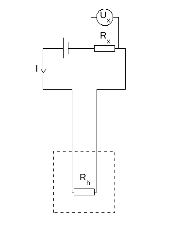
- The Schematic below (credit: Original Paper) shows the calibration configuration.
![Calibration Setup (Credit: Original paper)]()
- I'm using the following items
- Obtaining The Baseline
The original paper suggests doing a baseline calibration even if it was recorded during the calibration coefficient procedure, by doing so we eliminate any baseline drifts caused by a non-perfect balance between reference and sample vials. So we charge both vials with inert sample (in my case, Sand) and we measure a reading over a week or something.
I'll post results once I finish the procedure by next week.
Discussions
Become a Hackaday.io Member
Create an account to leave a comment. Already have an account? Log In.