Close
0%
0%

eeprog

An ATmega328-powered programmer for 28C64 EEPROM

Similar projects worth following
An ATmega328-powered programmer for 28C64 EEPROM, with open source hardware and software.

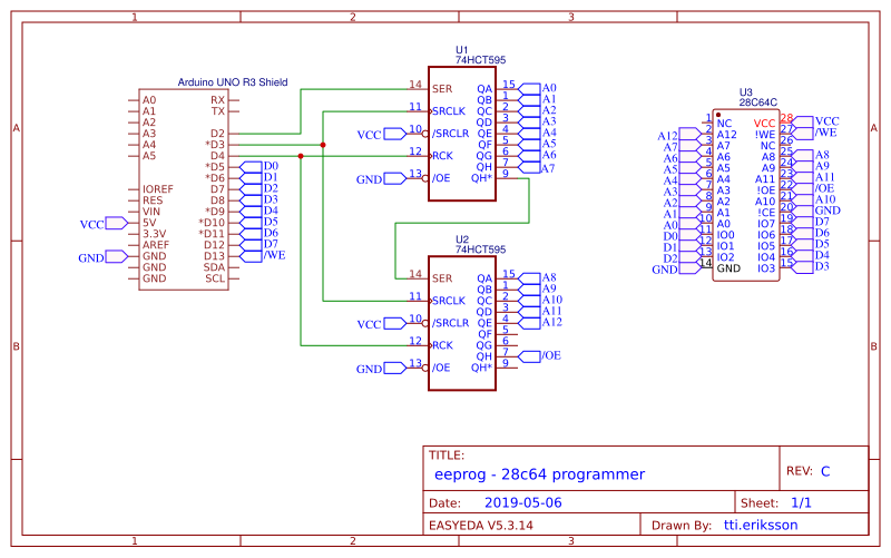
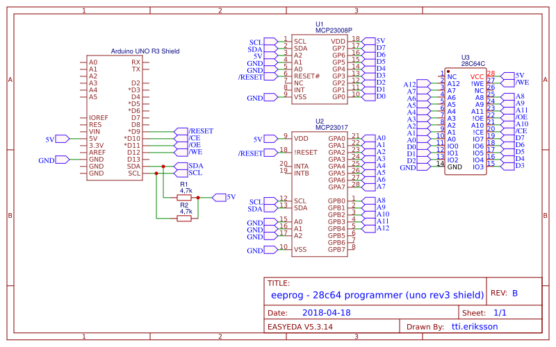
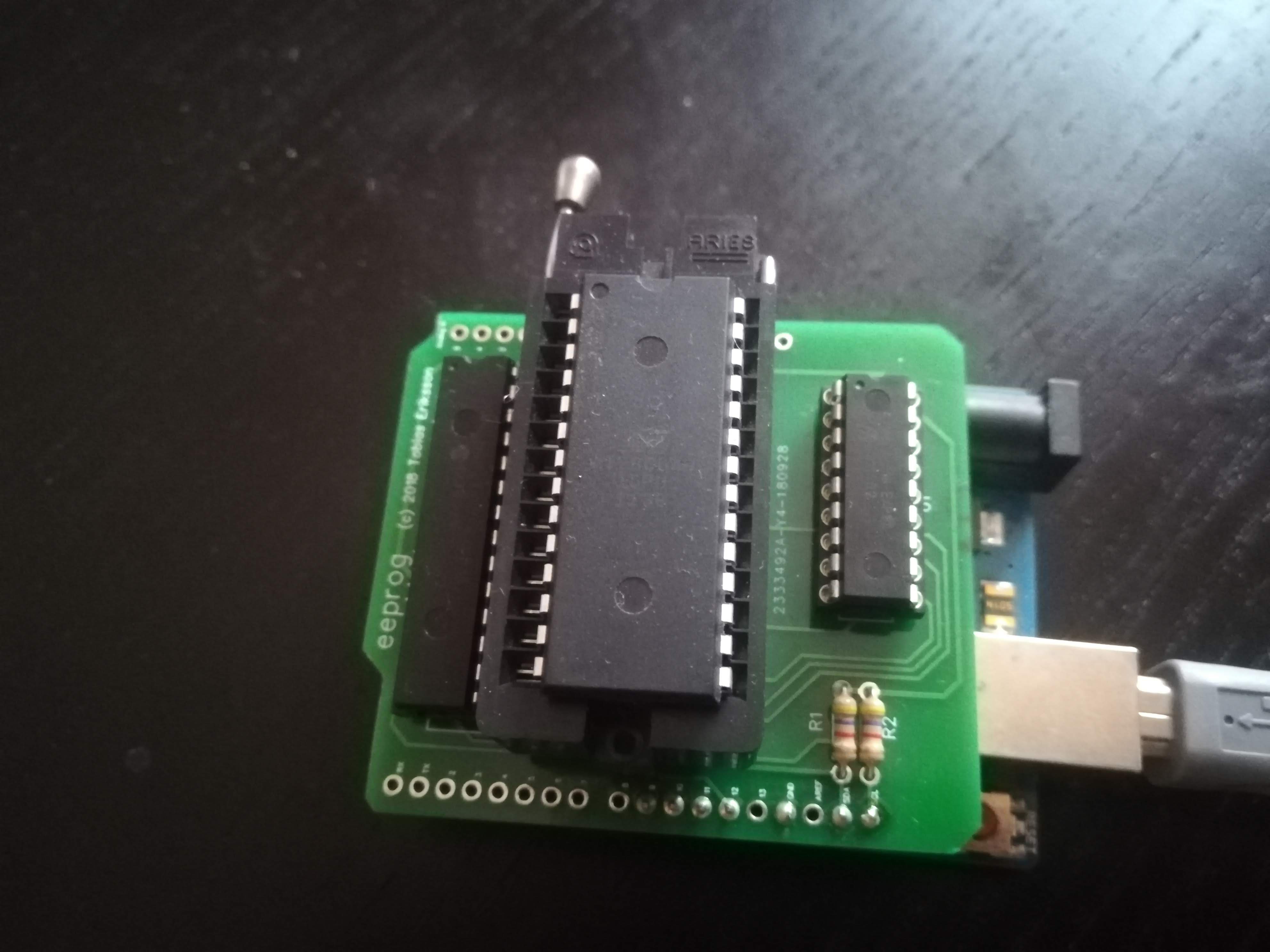
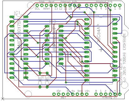
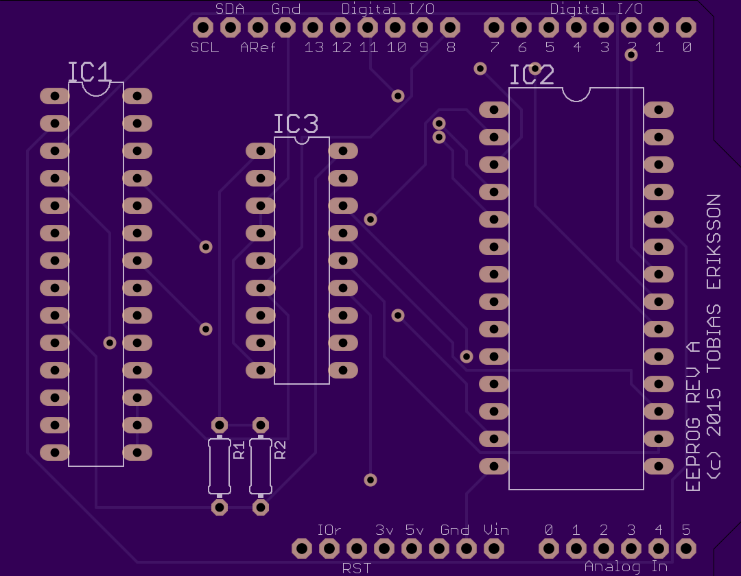
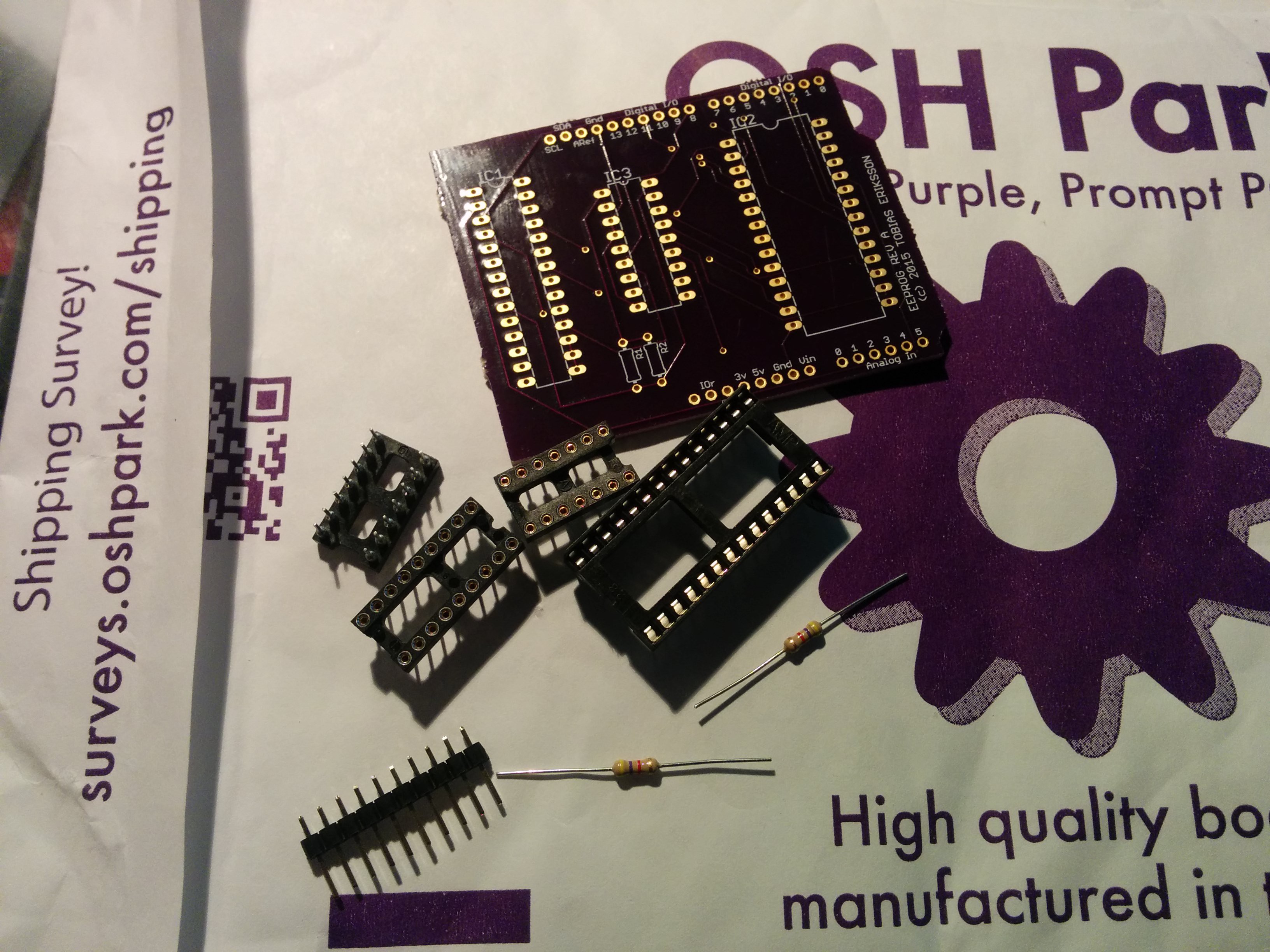
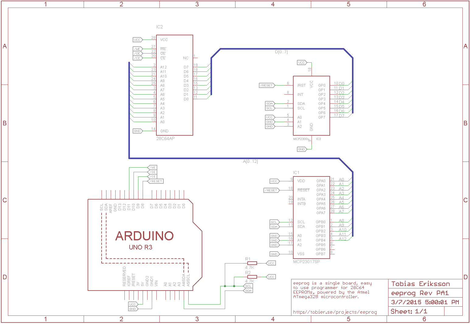
An open source hardware and software 28C64 EEPROM programmer, using the ATmega328 microcontroller. The goal of this project is to design and build an easy to use, single board programmer for 28C64 EEPROMs that could just be plugged in to a computer using a regular USB cable.

Gerber_PCB_20190514085347.zip

Gerber files from EasyEDA that I used to make my boards

Zip Archive - 84.76 kB - 05/14/2019 at 06:54

Download

  • 1 × PCB Shield, fits Arduino Uno R3
  • 2 × 74HC595 8-bit shift register with output latches
  • 2 × DIL-16 IC socket For the 74HC595
  • 1 × DIL-28 ZIF socket For the 28C64 EEPROM. Mounting the ZIF in another DIL-28 socket is recommended.
  • 11 × Header pins For mounting the shield to the Arduino Uno; I recommend soldering headers for all pins (even unused ones)

View all 6 components

  • Project Log #6 It's alive

    Tobias Eriksson05/14/2019 at 06:41 0 comments

    This project has existed in one form or another since 2015, and I'm happy to say that now I can finally consider this project feature complete.

    eeprog

    I've been through multiple revision of the board: the first two was based on the idea of using I/O expanders to deal with the lack of pins on the Arduino Uno, but the third revision is based on a much more simpler design I did back in the prototype phase in 2015 using shift registers for the address bus. I was also inspired by other designs using similar concepts which shows that a simpler design could work quite well (and helped me save pins).

    In the actual build I used 74HC595 instead of the HCT-chips I accidentally used in the schematic. All devices involved are CMOS so there is no need to be compatible with TTL levels.

    For now I have everything I need to program 28C64 EEPROMs, which means it can now be used for other project. I consider the hardware final at this point, and any improvements from now on will be on the software and firmware side. The programmer is not fast, but I've had issues with timing and therefore I feel it's better to be safe than sorry. The programmer verifies each block it's written to the EEPROM, so the design and software seems robust enough.

  • Project #5 Resurrection

    Tobias Eriksson01/27/2019 at 10:29 0 comments

    Welp, I can't believe I haven't updated in almost exactly two years. Time flies, since my last update I've moved to a new city which took up a lot of time and energy, and also my soldering station died. The project is not dead however, I even have new boards that I ordered from JLPCB.

    I made a new schematic that seemingly fixed the bug in the old one, and since I got a new soldering station during the holidays I've soldered it up.

    I'm starting to prototype the firmware; I've been wanting to try PlatformIO which I will use for the microcontroller code, and I will also implement a CLI tool and possibly a GUI. I've set up an organization on Github that will house the different repositories.

    I've said this before but let's hope it won't take a year or so for the next update :-)

  • Project log #4 Transfer protocol

    Tobias Eriksson01/25/2017 at 09:48 0 comments

    It's already been well of a year since I last made an update, but I promise the project is not abandoned! Fellow hacker @Erik Bartmann pointed out to me (thank you!) that I had an error in my revision A schematic. It turns out it made the entire circuit very unstable, which means I'll have to make a new revision of the schematic and order new boards. However, I'll leave the details of the schematic update to the next project log.

    Last time I worked on the project, I started prototyping a simple graphical user interface in Java. The data itself is sent over a serial interface, so I have the need of a simple transfer protocol. I could use something like XMODEM, but I think it's more fun to make something myself.

    I figured I wanted some sort of message passing protocol, so I sketched the following data structure:

    The first three data fields make up the header. The magic word is used to identify the start of a message (this is set to 0xBEEF). With this message structure, a message can be at most 262 bytes long, with a maximum payload of 256 bytes. The Message ID is used to decode the payload. After the payload there is a CRC-16 checksum, used to validate the data before potentially writing to the EEPROM. The checksum is calculated on the header and the payload together.

    The structure of the payload data depends on the message. With some messages the payload may even be zero-sized. Here's a table of the messages so far (there may be more coming):

    Message ID (hex)
    Name
    DirectionDescription
    0x00--Reserved (not used)
    0x01EraseTo deviceErase the entire EEPROM
    0x02EraseAckTo clientAcknowledge the erase
    0x03-0x0F--Reserved (not used)
    0x10WriteBlockTo deviceWrite a 64 byte data block to the EEPROM
    0x11WriteBlockAckTo clientAcknowledge the block write
    0x12-0x1F--Reserved (not used)
    0x20ReadBlockTo deviceRead a 64 byte data block from the EEPROM
    0x21ReadBlockAnswerTo clientRead response with 64 byte data
    0x22-0xFE--Reserved (not used)
    0xFF--Reserved (null message)

    I'll omit the message details and leave that to the avid source code reader to find out :-)

  • Project log #3 Revision A PCBs

    Tobias Eriksson08/31/2015 at 19:11 5 comments

    Wow. It's been a while since I posted an update. Since last time, I ordered PCBs from OSHPark. I found an excellent Arduino Uno template for Eagle that I used to make my shield.

    I designed the board using my schematics in Eagle. It's the first time I've made a board in Eagle; I used auto-routing and hoped for the best.

    To my eyes, the boards looked excellent when uploaded to OSHPark. Two weeks later, I got the boards in the mail!

    Here's one of the boards with some of the components. In the next project log, I hopefully have a finished version with mounted components to show.

  • Project Log #2

    Tobias Eriksson03/07/2015 at 16:05 0 comments

    I made this first schematic for the prototype that uses the Arduino Uno rather than a dedicated ATmega328 microcontroller. I haven't wired it up yet, but the circuit is quite simple so it should be no problems.

    I'll make another update when I've wired everything up on my breadboard :-)

  • Project Log #1

    Tobias Eriksson03/07/2015 at 13:01 0 comments

    For a long while I've wanted to do an electronics project. One of my goals is to make a complete computer from scratch, using an 8-bit microprocessor. But in order to build an 8-bit computer, I need a way to program ROM-chips. This is because when (most) CPUs boot up, they need to fetch the initial program from somewhere, and this somewhere is usually in ROM. My idea for a first project is therefore to make an ATMega-powered programmer for EEPROMs, specifically 286C4s. The entire project will be open source (both software and hardware).

    My plan is to develop this project in incremental steps, roughly as follows:

    • Prototype A on solderless breadboard, controlled by an Arduino Uno
    • Prototype B on solderless breadboard with dedicated ATmega328 microcontroller.
    • Standalone Revision A on stripboard

    It's likely that I will go on and produce Revision B with a custom printed circuit board.

    In my next update, I'll post the first schematic and a picture of the wired-up prototype A.

View all 6 project logs

Enjoy this project?

Share

Discussions

Ken Yap wrote 05/14/2019 at 07:11 point

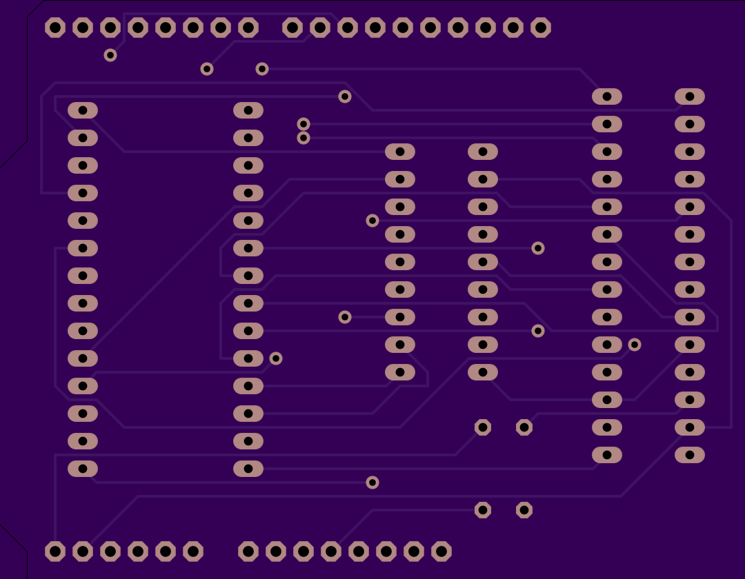
You've got two spare pins on the shift register so in principle you could modify the hardware to program up to 256kb chips? Unless the pinout is different which I haven't checked, the extra address lines would go to the NC pins on the ZIF socket.

  Are you sure? yes | no

Tobias Eriksson wrote 05/14/2019 at 07:20 point

Yes, you're right. As you say the 28C256 are on the NCs on the 28C64 so it's possible. An easy fix could just to be to add jumper wires underneath the board and it should just work (with some modification in the firmware to write 256kb rather than 64kb).

Good find, thanks! A stretch goal is to make this entire board stand-alone (without the Uno) which would be a good opportunity to add support for up to 28C256.

  Are you sure? yes | no

Ken Yap wrote 05/14/2019 at 07:23 point

👍 Nice project.

  Are you sure? yes | no

Erik Bartmann wrote 03/03/2016 at 13:15 point

Hi, there is a small bug in the circuit-diagram. Both pullup-resistors are connected to SCL. Great project! Erik

  Are you sure? yes | no

Tobias Eriksson wrote 03/03/2016 at 21:08 point

Thanks for the find, looks like I need to make a second revision of my board.

Oddly enough, the board seems to work somewhat OK. I wonder though if it will start randomly failing when writing a lot of data...

  Are you sure? yes | no

Tobias Eriksson wrote 03/07/2015 at 15:31 point

@davedarko No, there aren't enough I/O pins on the ATmega328. However, I'm going to use MCP23008 and MCP23017 I/O expanders for the data and address bus' respectively. I've seen others use shift registers for similar projects :-)

  Are you sure? yes | no

davedarko wrote 03/07/2015 at 17:44 point

cool cool :)

  Are you sure? yes | no

davedarko wrote 03/07/2015 at 14:44 point

I'm too lazy to google that, but do you have enough IOs for that? I've bought some 28c256 and noticed that I couldn't use an arduino mini (which is basically an atmega328 breakout board...) for that. interesting project! 

  Are you sure? yes | no

Similar Projects

Does this project spark your interest?

Become a member to follow this project and never miss any updates