 Kevin Kadooka
I've never met an old camera that I didn't like. Most were built without planned obsolescence in mind, are great values for the money, and produce beautiful photos without much coaxing. However, many tend to lack the creature comforts of more modern cameras - one of those being the exposure meter. Sure, you can carry around a light meter - but there's some convenience and elegance in having one built in to the camera.
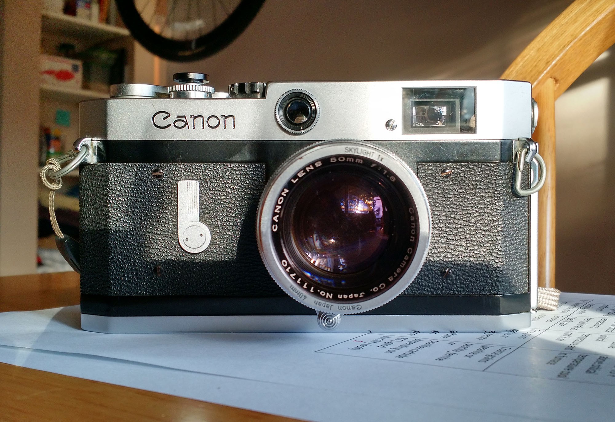
I purchased a Canon P rangefinder (circa 1960) with the intention of making it my "everyday carry" camera. Since it lacks a meter, I ended up having to tote around my TSL2561 light meter along with it, which is not a difficult task - but at times I would end up forgetting it at home. There's also the problem of having to put down the camera, pick up the meter, take a reading, adjust exposure settings, etc - it's not the smoothest process. Then I got to thinking, how great would it be if there were a meter built in to the camera?
Fast forward one or two decades from the era of the Canon P - mid 1970's and 80's - and TTL (through-the-lens) exposure metering becomes a commonplace feature in professional SLR cameras (think Olympus OM-2, Pentax LX, Nikon F(3?), Canon F-1, and the Leica M6 [not an SLR]). In these systems, the light entering the camera through the lens is reflected off of the shutter curtain, or off of the film itself, and the reflected light is measured by a silicon photodiode. In many of these systems, the exposure could be calculated on "on the fly" to account for changing light conditions - something we don't even see in modern DSLRs! No doubt there are many lessons to be learned from the cameras of yesteryear.
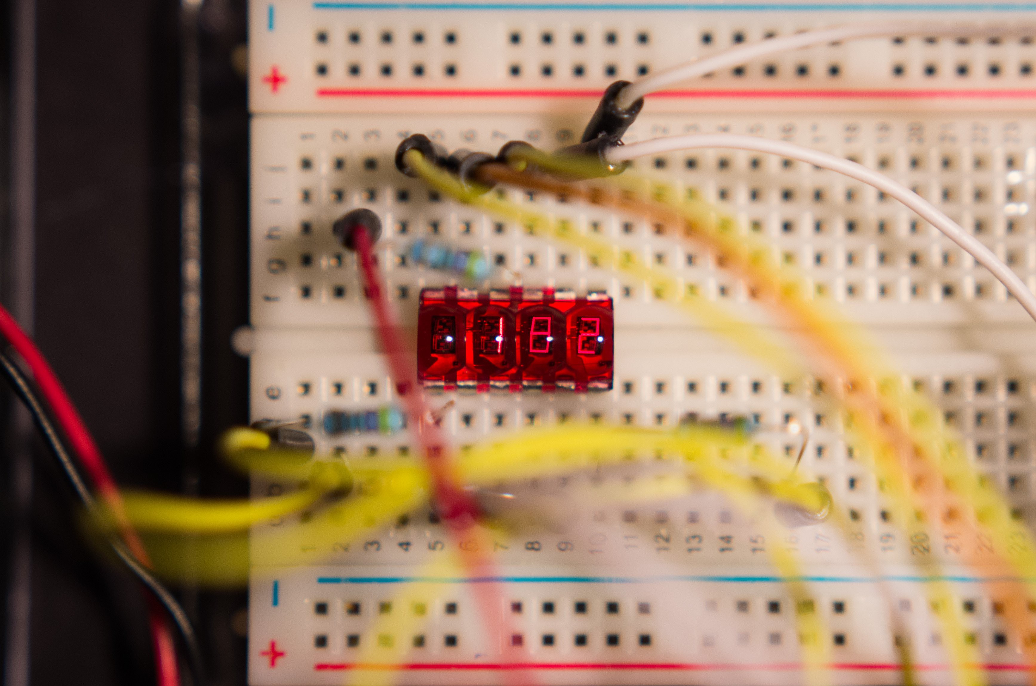
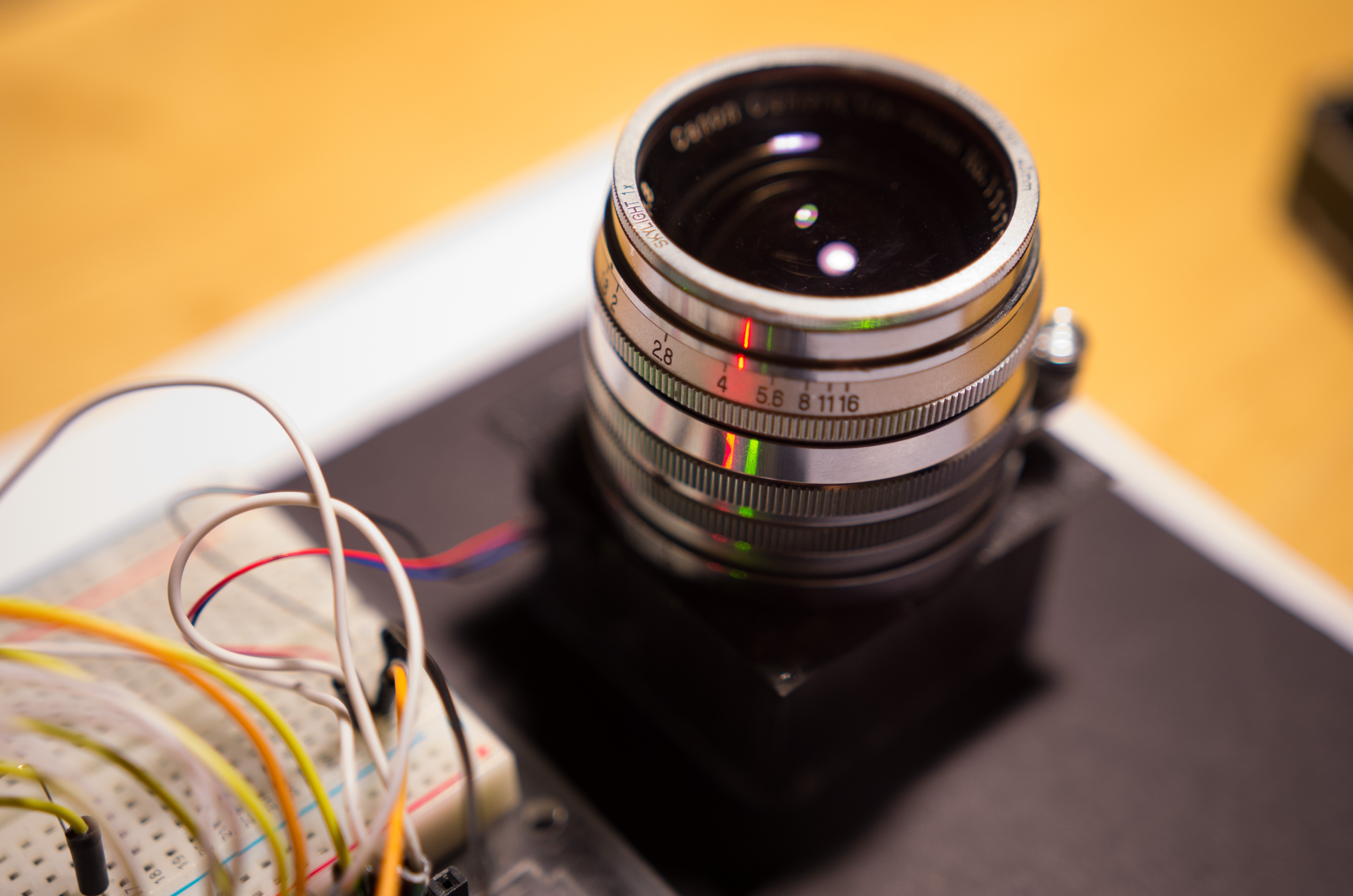
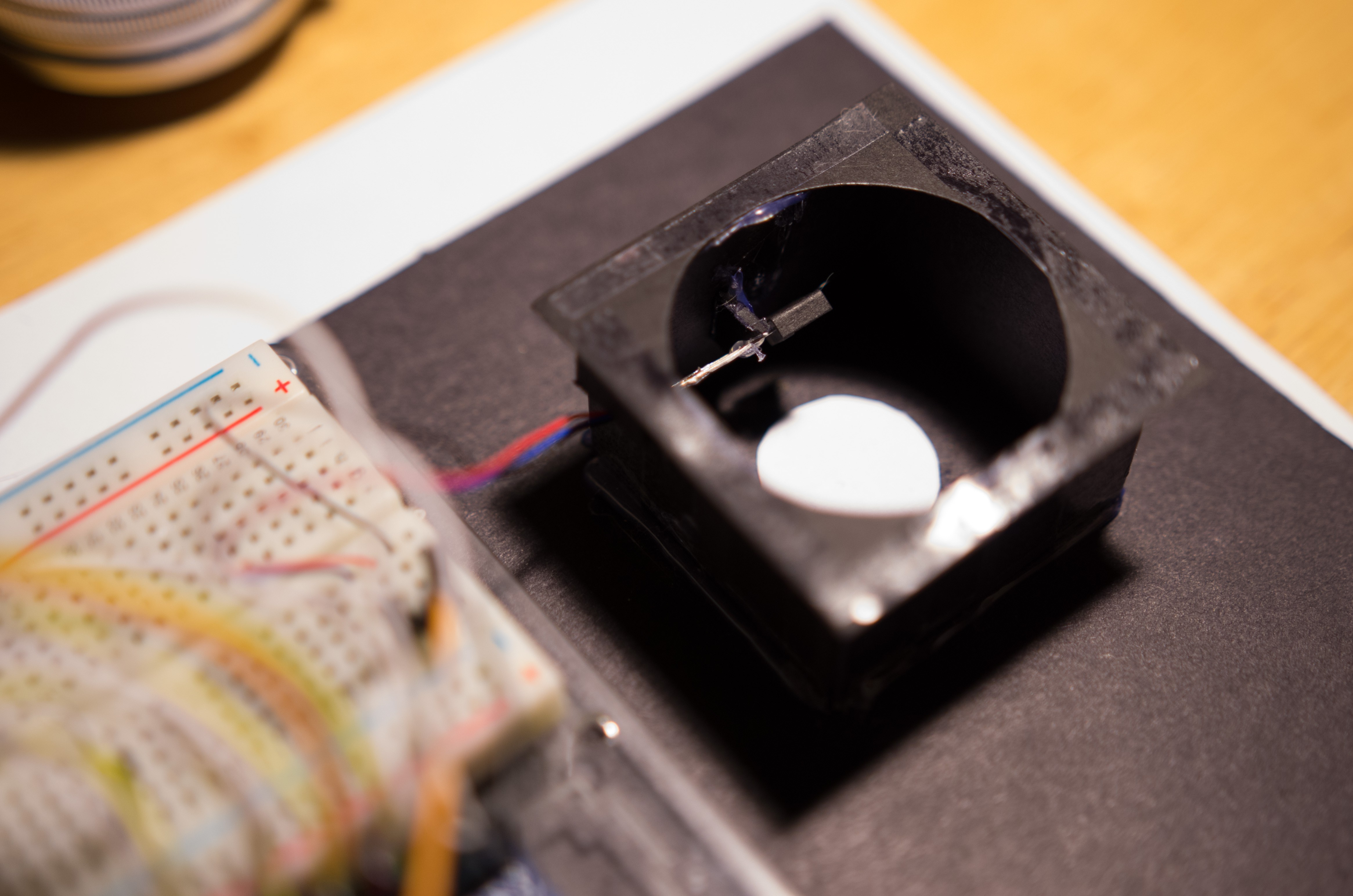
The TTL meter to be implemented in the Canon P will be nowhere as complex. The goal is to place a TSL235R light-to-frequency converter in the exposure chamber, which will measure the light reflected off of the shutter curtain. An Arduino-powered console will take the frequency reading from the TSL235R and convert it to illuminance, which is used to compute the required exposure time. The exposure time is then displayed on an HP QDSP-6064 bubble display.
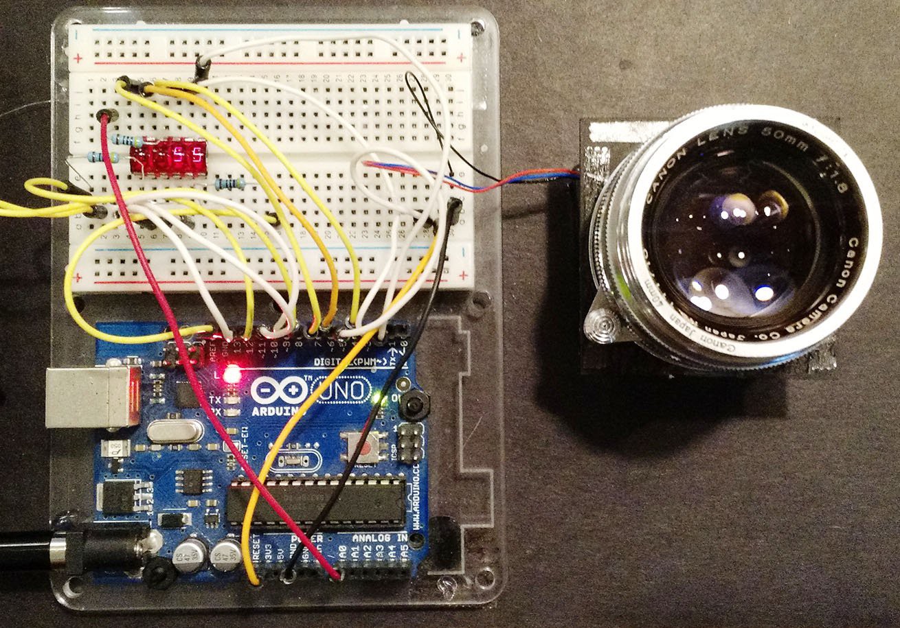
So far, I've made a testbed to check that the TSL235R has sufficient range to measure most exposure conditions. I originally thought that it might not have enough range on the bright end, but a quick test out in the sun proved otherwise. Looking forward to progressing with this project!
Discussions
Become a Hackaday.io Member
Create an account to leave a comment. Already have an account? Log In.
Not a dumb question at all. I couldn't find a TSL2561/91 breakout in a size that would fit comfortably in the exposure chamber, without blocking part of the frame. My soldering skills aren't good enough to solder to those tiny packages, either.
Are you sure? yes | no
This might be a dumb question: Why are you using a TSL235R instead of another TSL2561?
Are you sure? yes | no