 Kevin Kadooka
The title says it all. Time to hack up our pretty camera, and stuff the good bits in. We want the TSL235R to fit comfortably inside the exposure chamber, and route some wires through the body of the camera to connect to the console.
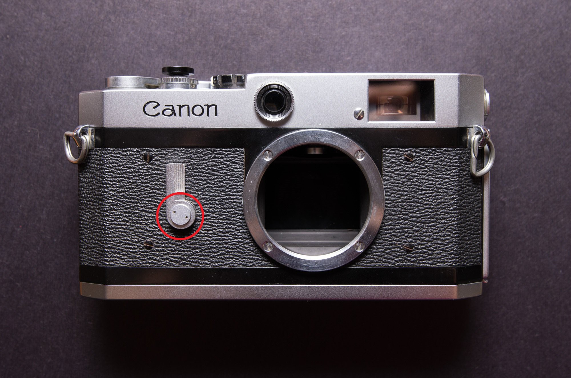
We begin by unscrewing the self-timer lever using a spanner wrench, and pulling the lever off.
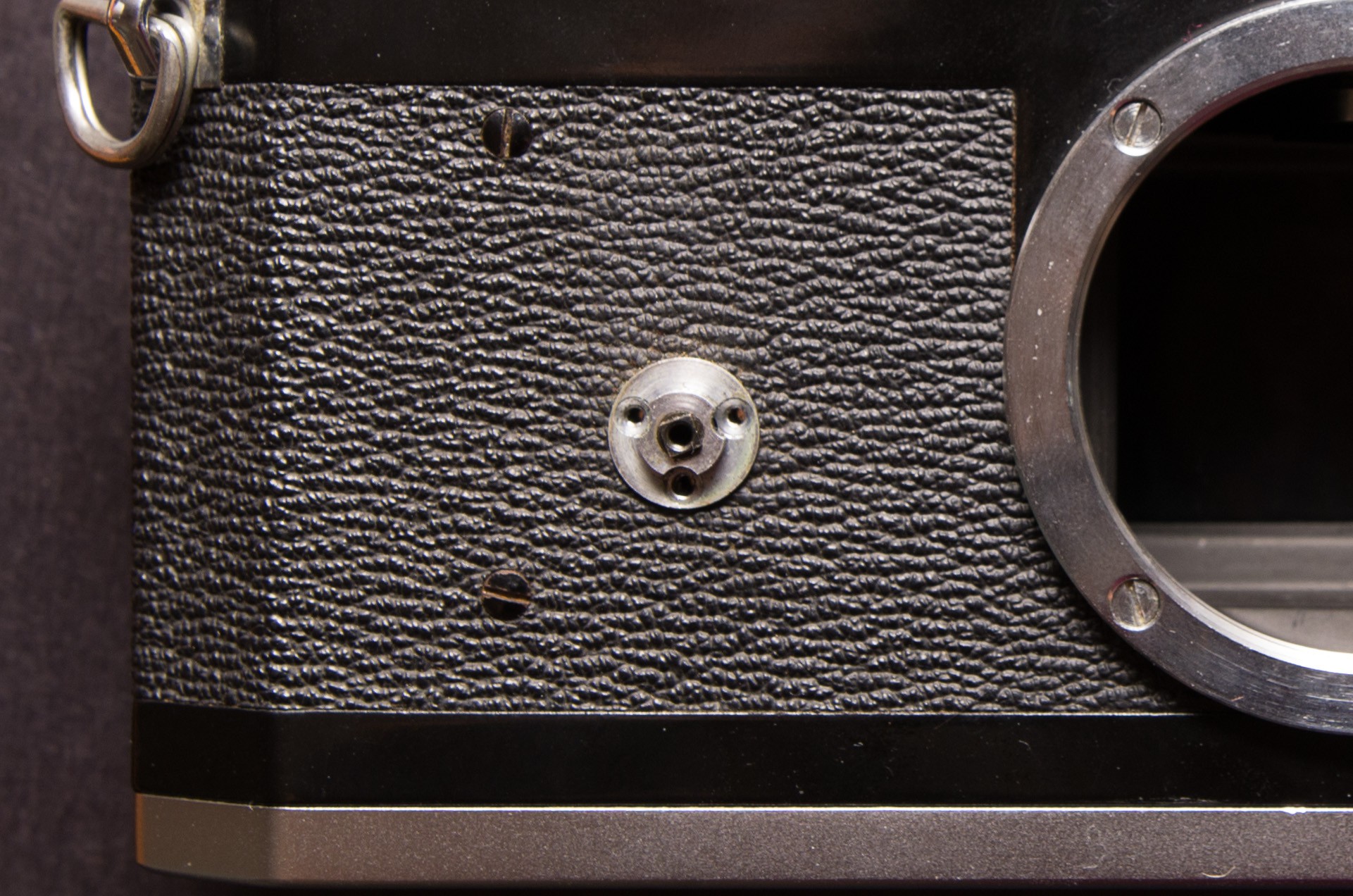
The three underlying screws in the self-timer assembly are then removed.
The mount is then removed. There is a brass shim, and a thinner silver shim beneath it to achieve the correct focus. Don't want to lose those!
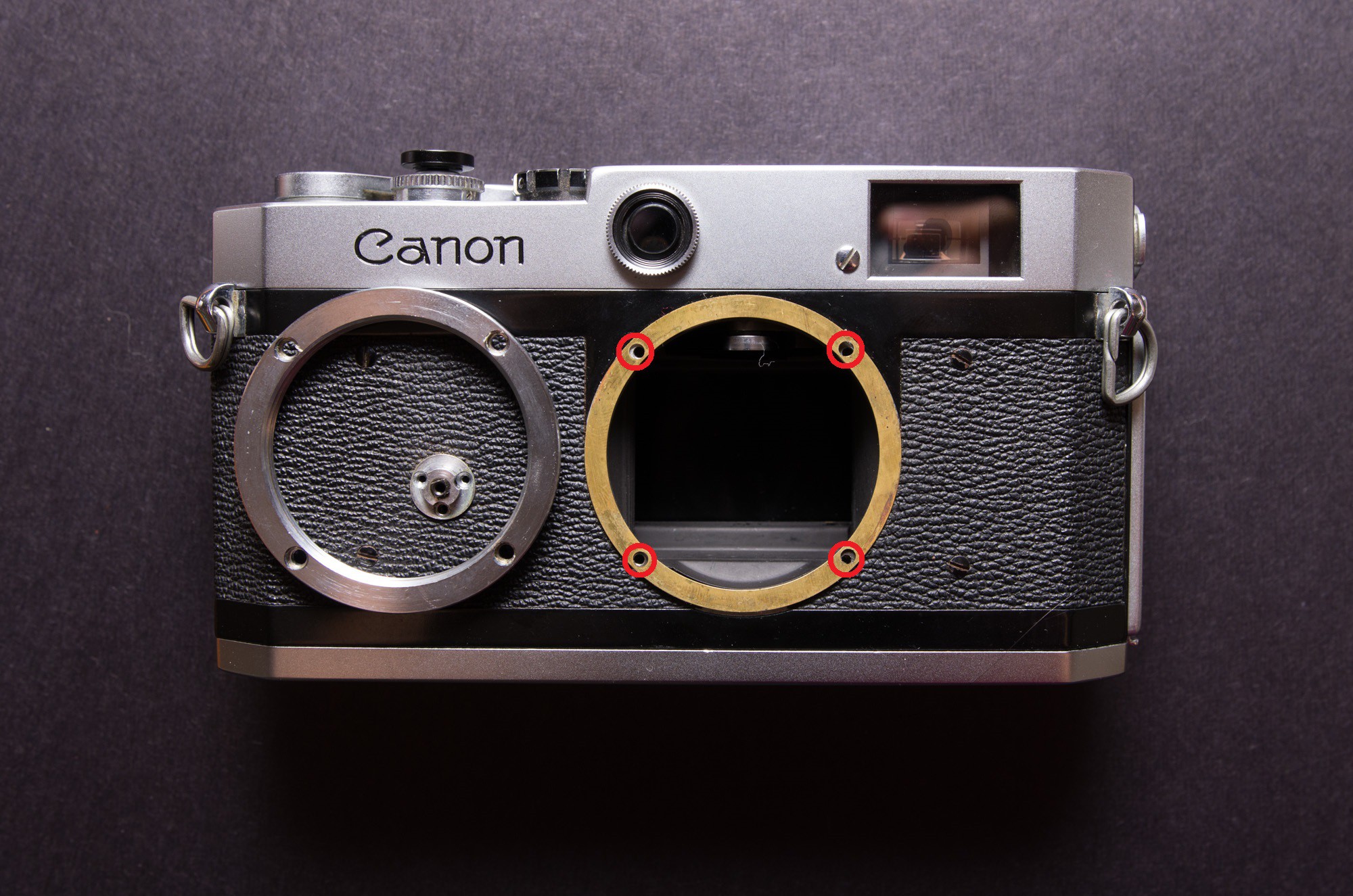
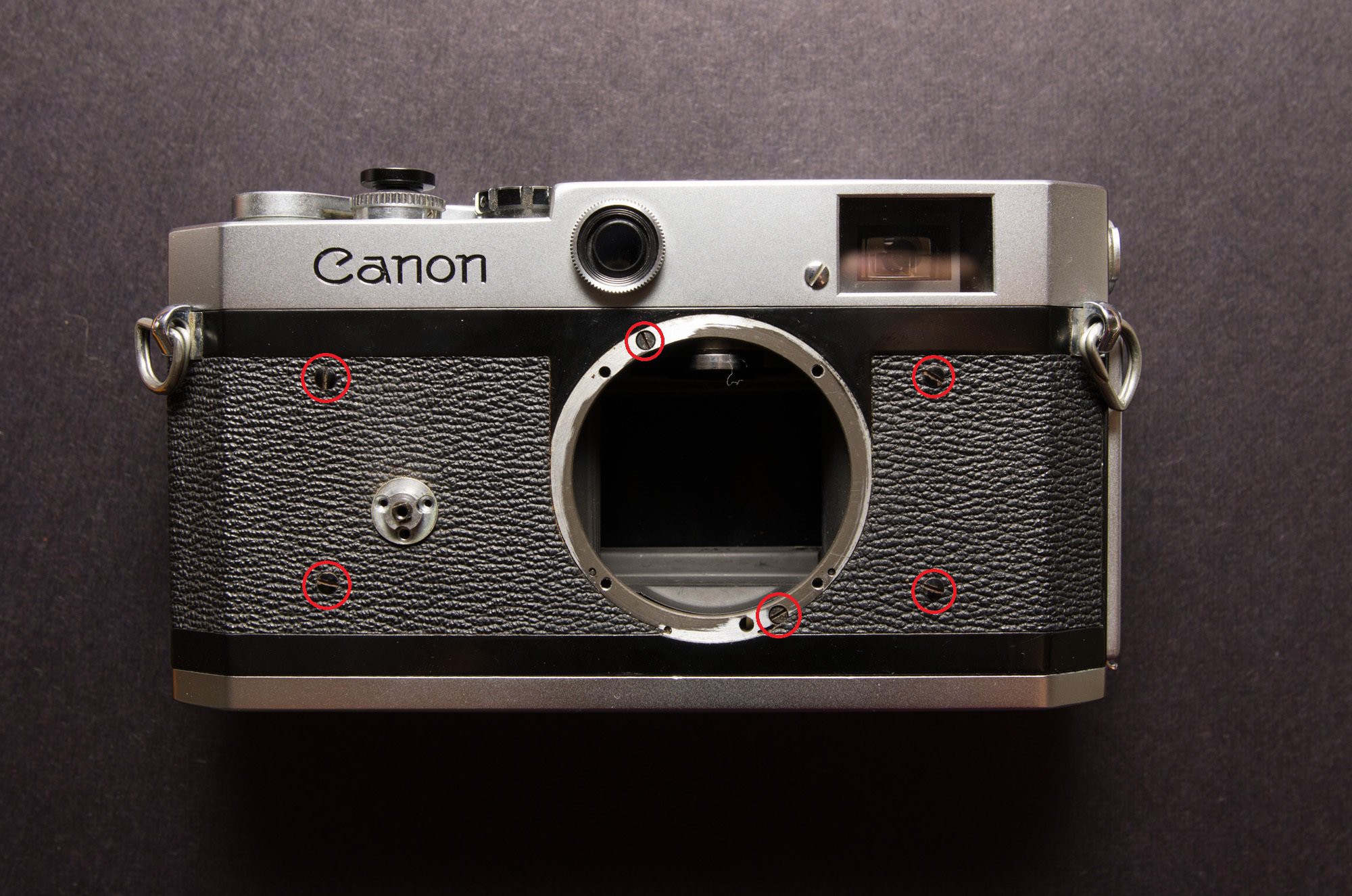
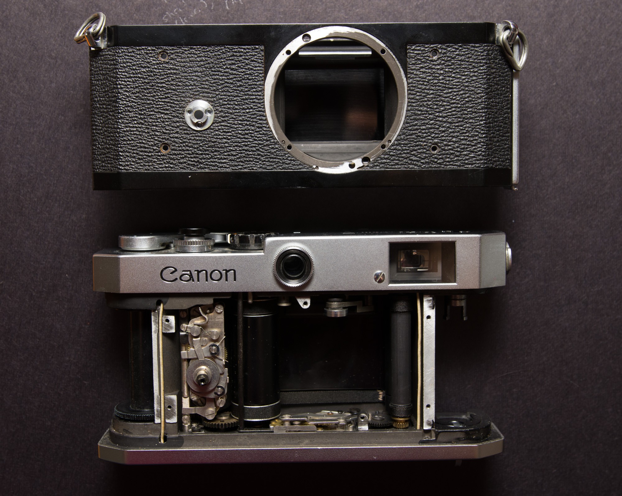
From there, six more screws are removed to free the "shell" of the camera.
After the shell is pulled free, the two halves look like this! Luckily we'll be carving up the top half only, which doesn't have any delicate optics or machinery.
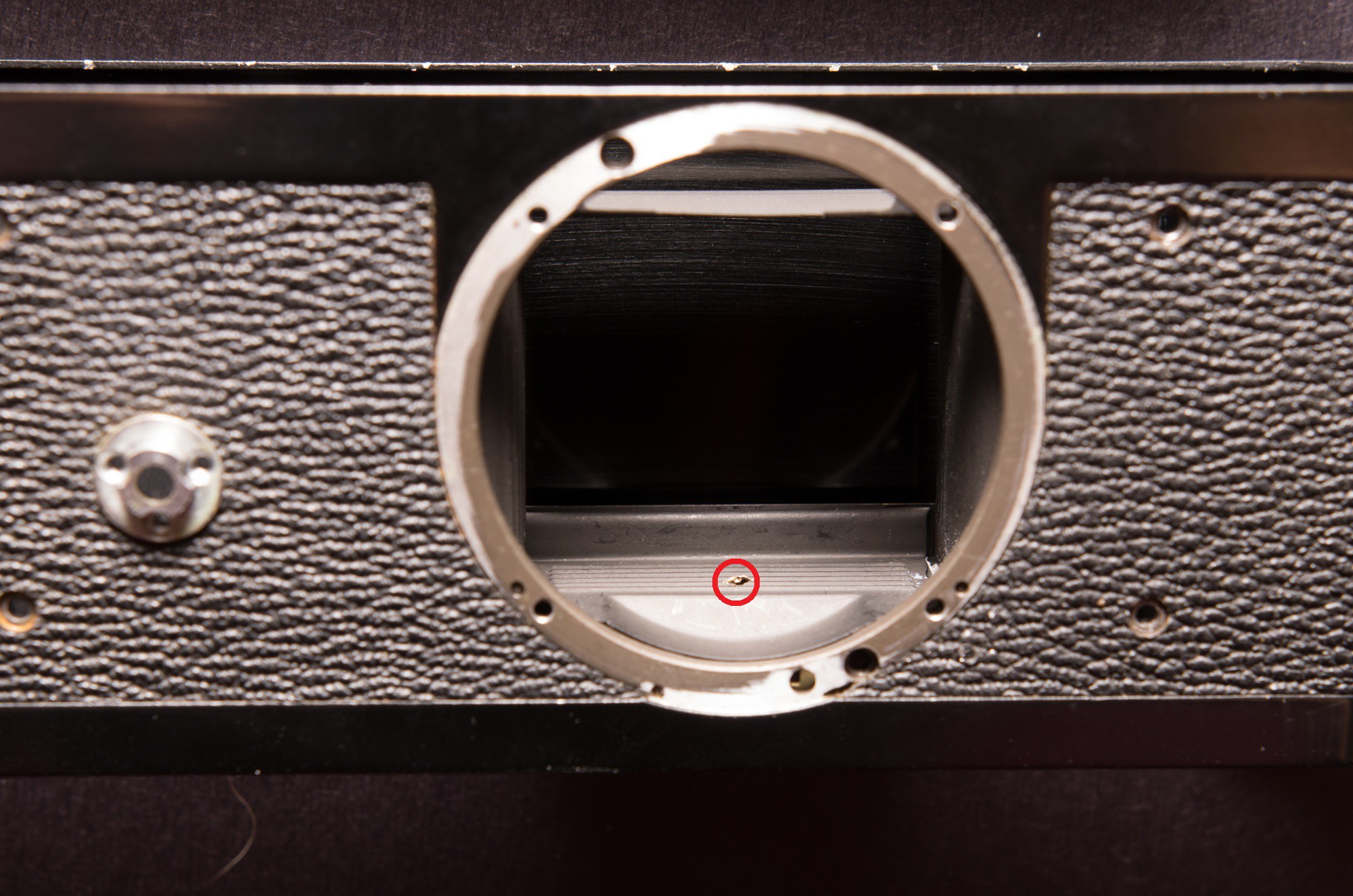
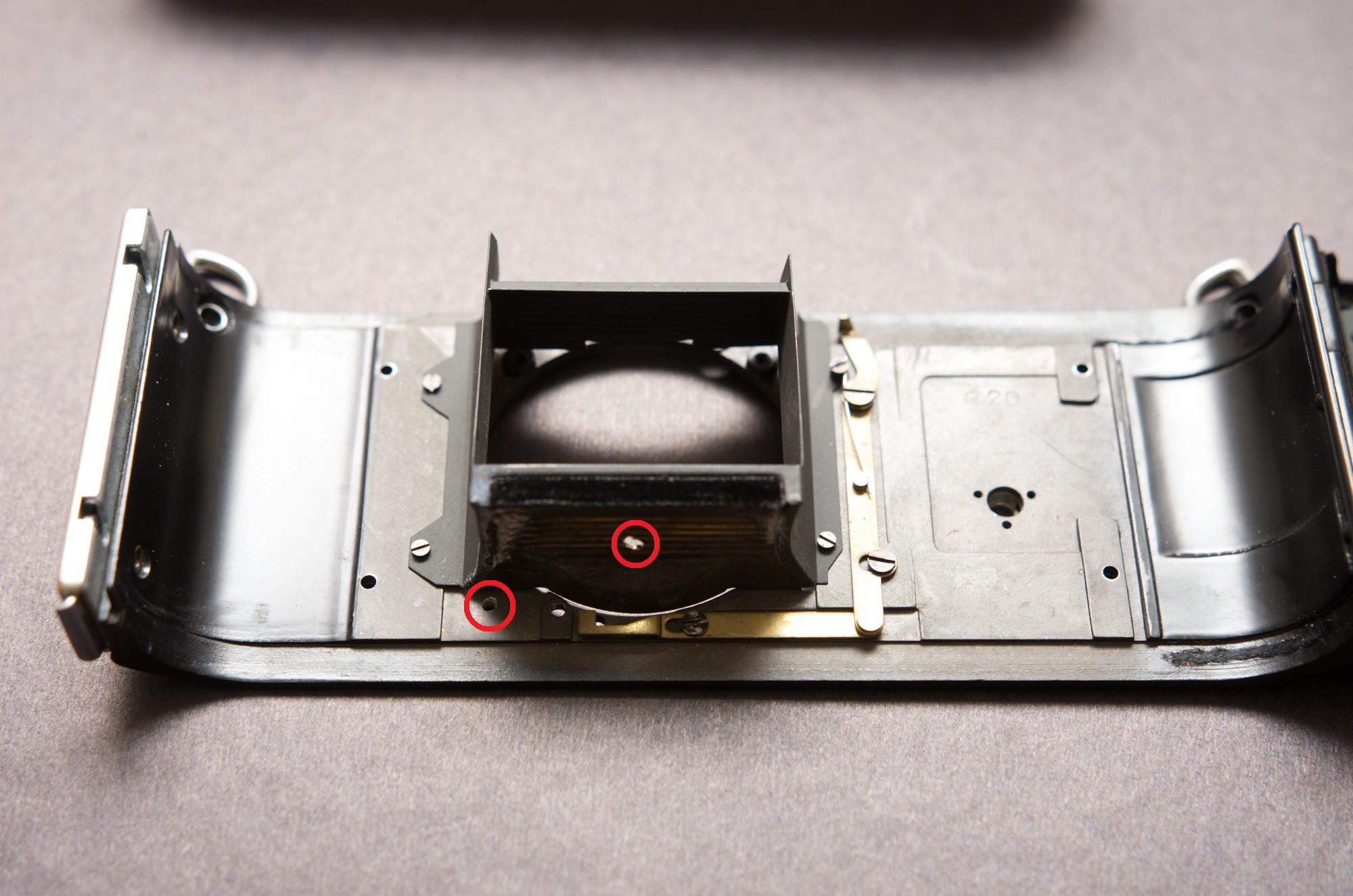
In the bottom of the exposure chamber, a small 1/16" hole is drilled to pass the wires of the TSL235R.
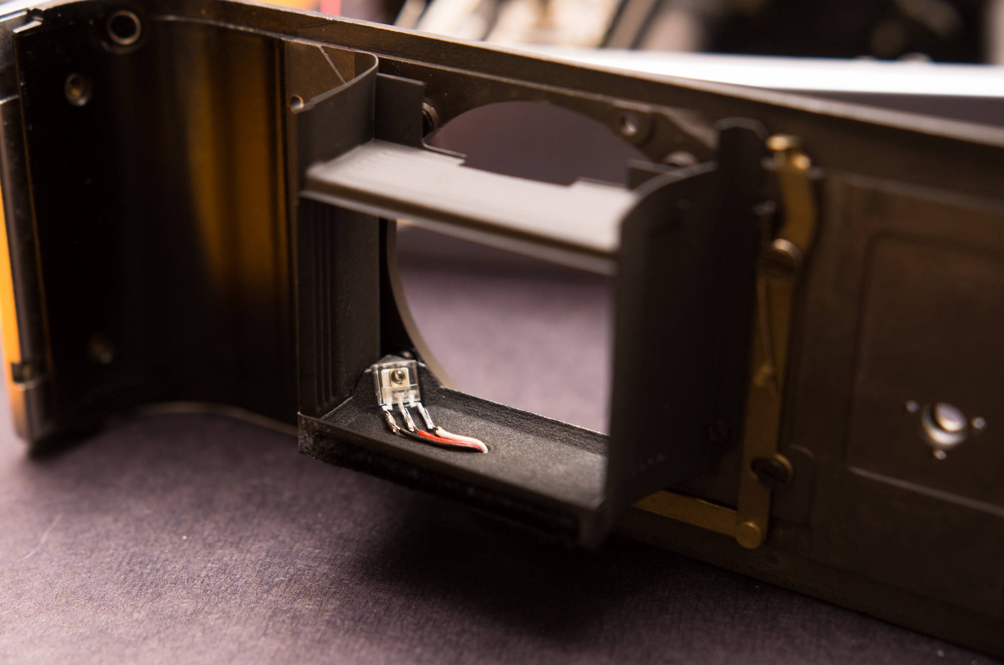
One more hole is drilled next to the lens mount, to allow the wires to exit the camera.
The TSL235R and its 3D printed mount are installed in the camera with a dab of white glue, and the wires are routed out of the camera.
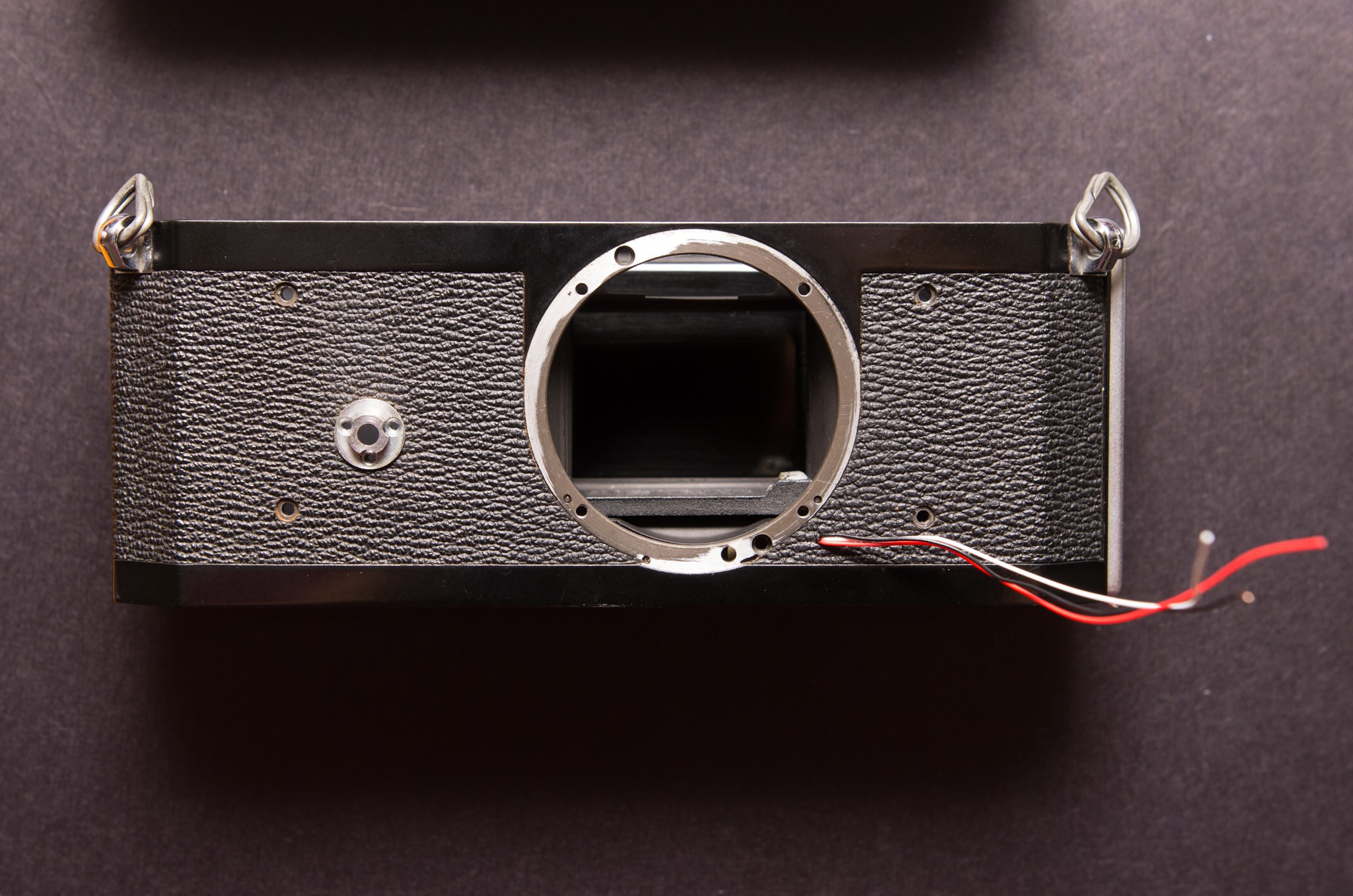
Have to be sure to keep the wires secure and tidy, so they don't accidentally come loose and get eaten by the shutter cocking mechanism. Just used a bunch of white glue, and a bit of Sugru to make sure light can't enter the camera.
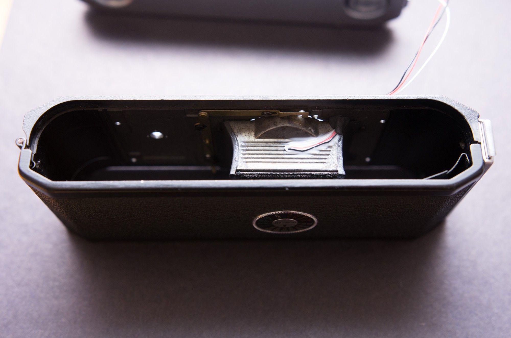
Here it is! The TSL235R light sensor pointed squarely at the center of the frame. I forgot to take a picture of the shutter curtain, which has a big white dot painted in its center, to reflect light back at the sensor.
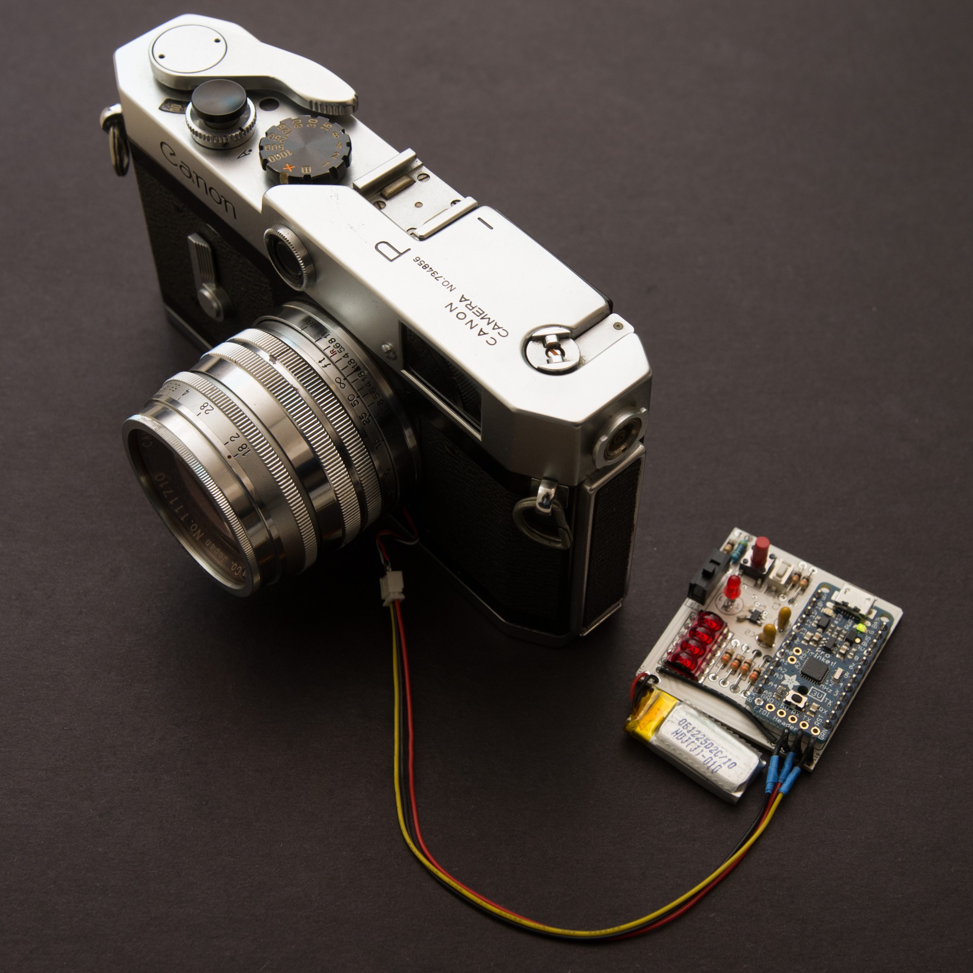
The previous steps are reversed, and here's the camera all put back together. No pieces or screws left over, thankfully :) The ends of the wires to the TSL235R are terminated by a 1.25mm pitch 3-pin JST connector (female), which the console plugs into.
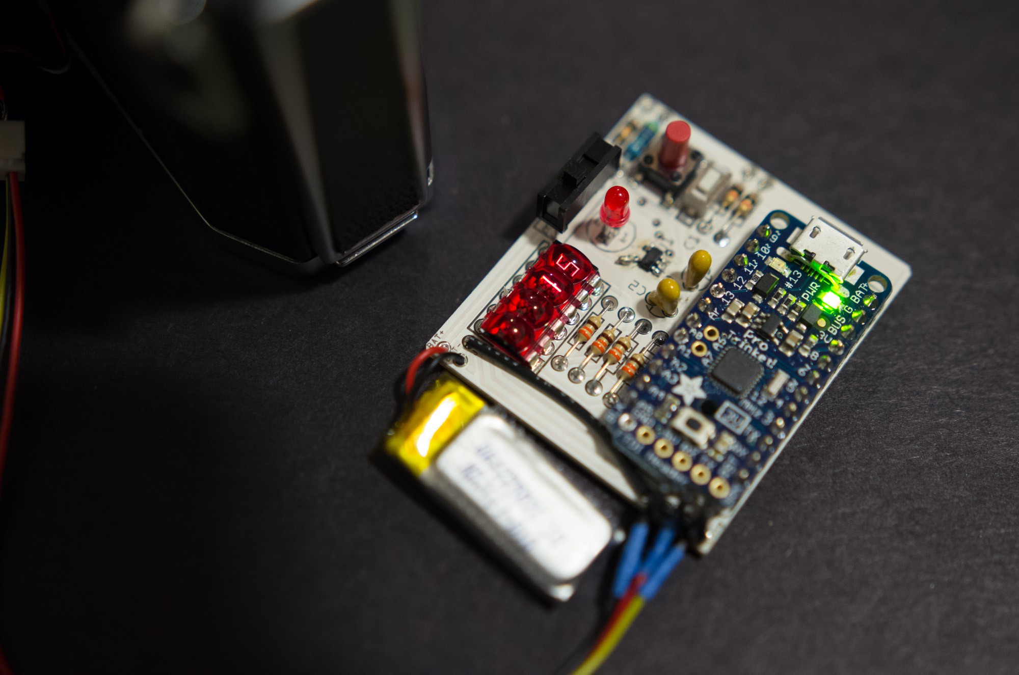
After programming the Trinket, we get our first shutter speed calculation! Too bad it's not correct, yet. Still need to calibrate things to make sure it's actually spitting out the right information.
The next tasks will be to mount the console and the female JST connector in their respective 3D-printed coverings, and finally calibrate the light meter. More later!
Discussions
Become a Hackaday.io Member
Create an account to leave a comment. Already have an account? Log In.