 will.sweatman
AUDIO IS NOT SAFE FOR WORK!
Naughty Duck
Posted by gigavolt

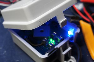
I know it doesn't look like much, but you'll be surprised when you here it talk! This was my latest creation for a Secret Santa gift exchange for the comedy site www.zug.com. I found this little talking toy duck at a local goodwill. When you pressed little button on it's foot, it would sing a silly song with it's mouth moving in sync with the words, and flap its wings. I wanted it to say something different, something funny. I used the following core components.
- SOMO-14D audio player
- PIC16F628
I picked the SOMO14D audio player because I've used them before and know how to code them. You can pick them up from Sparkfun for about $25. I picked the 16F628 because I happened to had a few laying around. This would turn out to be a mistake, as you will see later.
The stock duck works as follows: There are two DC motors and a bunch of gears. One motor for the mouth, and one that flaps the wings. The mouth motor has a spring that keeps it closed. Both motors go to a little pcb with a BBIC (Black Blob Integrated Circuit). The switch on the foot also goes to the pcb, and starts/stops the ducks routine.
One thing I learned from hacking these type of toys in the past is that it's best to use the stock PCB to drive the motors. And I did just that. It was a trivial task finding the signals for the mouth and wings on the stock PCB. I would tap into these and feed my own signals to the mouth and wings driver transistors. I would use the SOMO-14D to feed my own audio to the speaker. And wala! A hacked duck!
Known Issues
So, the project was not without its problems, and I hope some of you might be able to shed some light on them.
- One of my biggest issues was current draw when the power switch was on, but the duck was not doing anything. It draws about 11omA! And that's with the PIC in sleep mode. The result is you have to remove power from the board or the batteries will die in a couple of days. I don't know why it's drawing so much current. Please leave ideas and suggestions in the comments to reduce it.
- The SOMO-14D needs 3.3v and the PIC needs 5v. Naturally, I used a 6v battery supply and a 3.3 regulator for the SOMO-14D. A protection diode on the PIC keeps it's voltage around 5.5v. I have a serial and a clock line running from the PIC to the SOMO-14D (see schematic below). I used in line resistors like the datasheet suggests. I also put in a couple protection diodes. But somehow the voltage on the VCC pin of the SOMO-14D would jump up to around 4.3 volts when the PIC sends the PLAY command to the SOMO. This is WAY above the maximum allowed voltage specified by the data sheet. Now, it seemed to work just fine. But I still don't understand why it does this. And if you build this circuit, be aware of it. Maybe somebody can find my mistake and post in the comments.
Technical Details
Layout of board and schematic were done in Eagle.
PIC was programmed in C in MPLAB using CCS compiler & a ICD2 programmer.
Board was ordered through the Dorkbot service.
![]() Board from Dorkbot PCB
Board from Dorkbot PCB
![]() Surface mount done in toaster oven
Surface mount done in toaster oven
![]() Click for full size
Click for full size
If any of the links below are dead, send an email to gigavolt <at> comcast.net. I will send you the files or fix the links.
Get the Source code here.
Get the Eagle schematic here.
Get the Eagle board file here.
Get the SOMO-14D Eagle layout here.
HAPPY HACKING!
-gigavolt
UPDATE
Thanks to everyone who commented! I needed at least 6 volts to power the actual duck, but I never thought about using the 3.3 regulator to power both the PIC and the SOMO board. Looks like current draw issue was coming from the regulator itself. Thanks to "dmo" for pointing this out. And it would have been best if I used a voltage divider between the PIC and SOMO. Thanks to all of you who pointed this out!
Also, thanks to Hackaday and Buildlounge for posting my project.
 KingOfKYA(Travis K. )
 CaptMcAllister
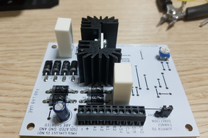
 Gabriel D'Espindula
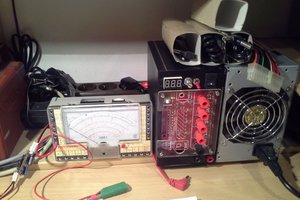
 Stefan Lochbrunner