 Pete Hoffswell
This project uses the ESP-01 to control the garage door opener as well as sense when the door is open or closed.
The ESP-01 talks via wifi to an OpenHAB controller that monitors door status as well as sends door open/close commands.
Use an ESP-01 micro controller to control your Garage Door
Already have an account? Log in.
To make the experience fit your profile, pick a username and tell us what interests you.
This project uses the ESP-01 to control the garage door opener as well as sense when the door is open or closed.
The ESP-01 talks via wifi to an OpenHAB controller that monitors door status as well as sends door open/close commands.
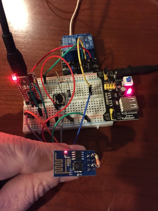
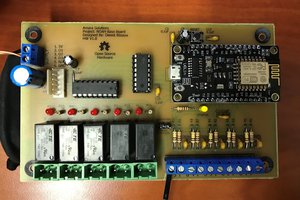
The controller has been installed and running great for a few days now. Stability looks to be very good. If I can get my hands on a 3.3v relay and a strong 3.3v power supply, this could move from the bread board to a perf-board.
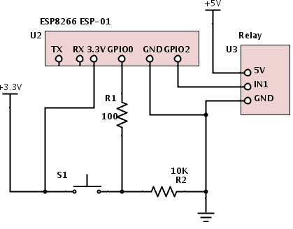
Wire the ESP-01 as follows. Go ahead and leave your TTL converter connected so you can continue programming and debug.
Connect your ESP-01 to your TTL serial converter and flash your ESP-01 with NodeMCU
Follow Marc's good instruction on how to load NodeMCU onto your ESP-01 at https://importhack.wordpress.com/2014/11/22/how-to-use-ep8266-esp-01-as-a-sensor-web-client/
ESPlorer is a great way to program the ESP-01. Get ESPlorer IDE running, so you can access and program the ESP-01.
Program your ESP with the following code -
Change the ip address of the M:connect command to match the ip address of your MQTT broker.
-- Garage Door controller version 2/15/15 pete@hoffswell.com
-- GPIO0 is connected to switch with internal pulldown enabled
gpio.write(3,gpio.LOW)
gpio.mode(3,gpio.INPUT,gpio.PULLDOWN)
--GPIO2 is connected to Relay
gpio.mode(4,gpio.OUTPUT)
gpio.write(4,gpio.HIGH)

print("Program Start")

-- Start up mqtt
m = mqtt.Client("ESP1", 120, "user", "password")
m:lwt("/lwt", "offline", 0, 0)
m:connect("192.168.15.22", 1883, 0, function(conn) print("mqtt connected")
   m:subscribe("openhab/garage/relay1",0, function(conn) print("subscribed relay1")
   end)
end)

-- Reconnect to mqtt server if needed
m:on("offline", function(con) print ("reconnecting...")
   tmr.alarm(1, 10000, 0, function()
      m:connect("192.168.15.22", 1883, 0, function(conn) print("mqtt connected")
         m:subscribe("openhab/garage/relay1",0, function(conn) print("subscribed relay1")
         end)
      end)
   end)
end)

 -- Switch Trigger
gpio.trig(3, "both",function (level)
   state = gpio.read(3)
   m:publish("openhab/garage/switch1",state,0,0)
   print("Sent openhab/garage/switch1 " .. state )
end)

-- MQTT Message Processor
m:on("message", function(conn, topic, msg)
   print("Recieved:" .. topic .. ":" .. msg)
   if (msg=="GO") then  -- Activate Door Button
      --print("Activating Door")
      gpio.write(4,gpio.LOW)
      tmr.delay(1000000) -- wait 1 second
      gpio.write(4,gpio.HIGH)
   else
      print("Invalid - Ignoring")
   end
end)

questions.....there is a resistor soldered onto the 8266 board, what is its value and purpose. Im setting up to try an build this myself.

Hi Dwayne -
The contact switch that senses the door open/closed state simply completes the circuit. You can install it either way.
For the init.la file, you might need to put in a delay?

I got the switch working properly now. i didn't know the resistor were needed to be left in circuit. works like a charm now. this is awesome, and will be adapting to make this run my electric gates. Thank you very much (although i found one that you wire into the remote control for the gates, but cant seem to find it now)
how would i add a delay?
i believe its the esp01 version that i have (black 1mb version) and the way (Settings) i am flashing the nodemcu firmware. since the tutorials are a little outdated (now you must build your own custom firmware) and mostly are for the 512kb version, i think i am doing something wrong.
in ESPlorer it gives me the cant detect firmware version, and then once i reload it once or twice i am able to manually start the init.lua file. ive posted in the esp8266 forum, and there does not seem to be alot of movement.
I have a question on how to wire the sensor. One side goes to positive or negative?
Also I got this working wonderfully when I start the program thru esplorer. But init.la does not load by itself
 unfoundbug
 Alexander Else
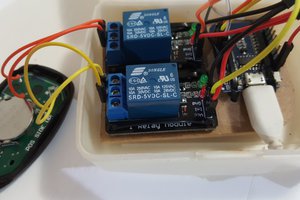
 Dewet
Dewet
Any help with the MQTT set up. I keep hitting a wall with it HARD. I can get it running on my server but cant seem to get it to do much else. Need advice.