-
1Step 1
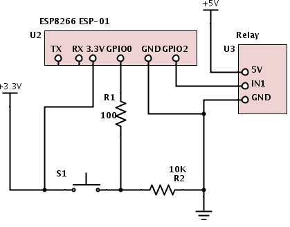
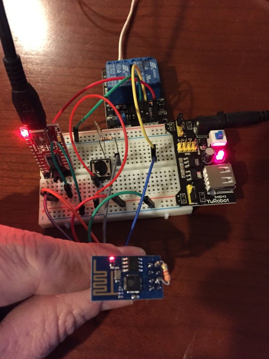
Wire the ESP-01 as follows. Go ahead and leave your TTL converter connected so you can continue programming and debug.
![]()
-
2Step 2
Connect your ESP-01 to your TTL serial converter and flash your ESP-01 with NodeMCU
![]()
Follow Marc's good instruction on how to load NodeMCU onto your ESP-01 at https://importhack.wordpress.com/2014/11/22/how-to-use-ep8266-esp-01-as-a-sensor-web-client/
ESPlorer is a great way to program the ESP-01. Get ESPlorer IDE running, so you can access and program the ESP-01.
-
3Step 3
Program your ESP with the following code -
Change the ip address of the M:connect command to match the ip address of your MQTT broker.
-- Garage Door controller version 2/15/15 pete@hoffswell.com -- GPIO0 is connected to switch with internal pulldown enabled gpio.write(3,gpio.LOW) gpio.mode(3,gpio.INPUT,gpio.PULLDOWN) --GPIO2 is connected to Relay gpio.mode(4,gpio.OUTPUT) gpio.write(4,gpio.HIGH) print("Program Start") -- Start up mqtt m = mqtt.Client("ESP1", 120, "user", "password") m:lwt("/lwt", "offline", 0, 0) m:connect("192.168.15.22", 1883, 0, function(conn) print("mqtt connected") m:subscribe("openhab/garage/relay1",0, function(conn) print("subscribed relay1") end) end) -- Reconnect to mqtt server if needed m:on("offline", function(con) print ("reconnecting...") tmr.alarm(1, 10000, 0, function() m:connect("192.168.15.22", 1883, 0, function(conn) print("mqtt connected") m:subscribe("openhab/garage/relay1",0, function(conn) print("subscribed relay1") end) end) end) end) -- Switch Trigger gpio.trig(3, "both",function (level) state = gpio.read(3) m:publish("openhab/garage/switch1",state,0,0) print("Sent openhab/garage/switch1 " .. state ) end) -- MQTT Message Processor m:on("message", function(conn, topic, msg) print("Recieved:" .. topic .. ":" .. msg) if (msg=="GO") then -- Activate Door Button --print("Activating Door") gpio.write(4,gpio.LOW) tmr.delay(1000000) -- wait 1 second gpio.write(4,gpio.HIGH) else print("Invalid - Ignoring") end end) -
4Step 4
Configure OpenHAB. (These instructions assume you have a OpenHAB server already. For more info on openhab, visit https://github.com/openhab/openhab/wiki/Quick-Setup-an-openHAB-Server)
- Set up MQTT Broker if you have not done so already
- Set up the OpenHAB configuration files as follows, to display door open/closed switch status, and send door button presses.
- Configure an openhab rule to send you a tweet when the door is open or closed for testing. Send you a tweet when the door is left open for 5 minutes
Sitemap:
Text item=Switch1 Switch item=Relay1 mappings=[ON="Go!"]Items:Number Switch1 "Door Status [MAP(switch.map):%d]" <garagedoor> (Sensors) {mqtt="<[mqttbroker:openhab/garage/switch1:state:default]", autoupdate="false"} Switch Relay1 "Garage Door" <garagedoor> (All) {mqtt=">[mqttbroker:openhab/garage/relay1:command:ON:GO]", autoupdate="false"}transform/switch.map:
0=open
1=closed
rules
var Timer timer = null rule "Tweet Switch Status" when Item Switch1 changed then var SimpleDateFormat df = new SimpleDateFormat( "YYYY-MM-dd HH:mm:ss" ) var String Timestamp = df.format( new Date() ) if(Switch1.state == 0) { sendDirectMessage('yourtwittername', 'Switch Open ' + Timestamp) timer = createTimer(now.plusSeconds(300)) [| // start timer and watch for 5 minute timeout sendDirectMessage('yourtwittername', 'Door open too long!') ] } else if(Switch1.state == 1) { sendDirectMessage('yourtwittername', 'Switch Closed ' + Timestamp) if(timer!=null) { // cancel timer, door is closed timer.cancel timer = null } } end -
5Step 5
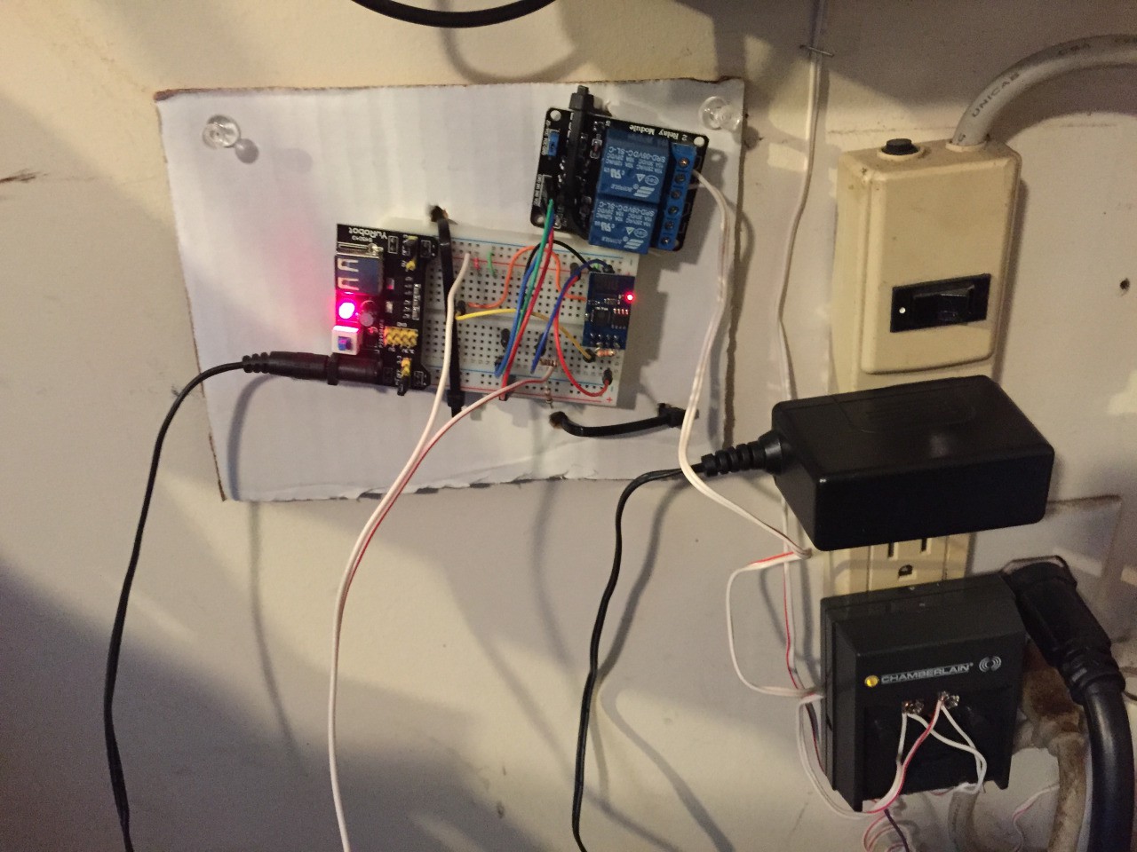
Connect it up to the garage. The relay will connect to your garage door opener exactly the same way the push button on the wall does. You should see the two wires without too much trouble. I just connected to the wireless controller that was plugged in the wall -
![]()
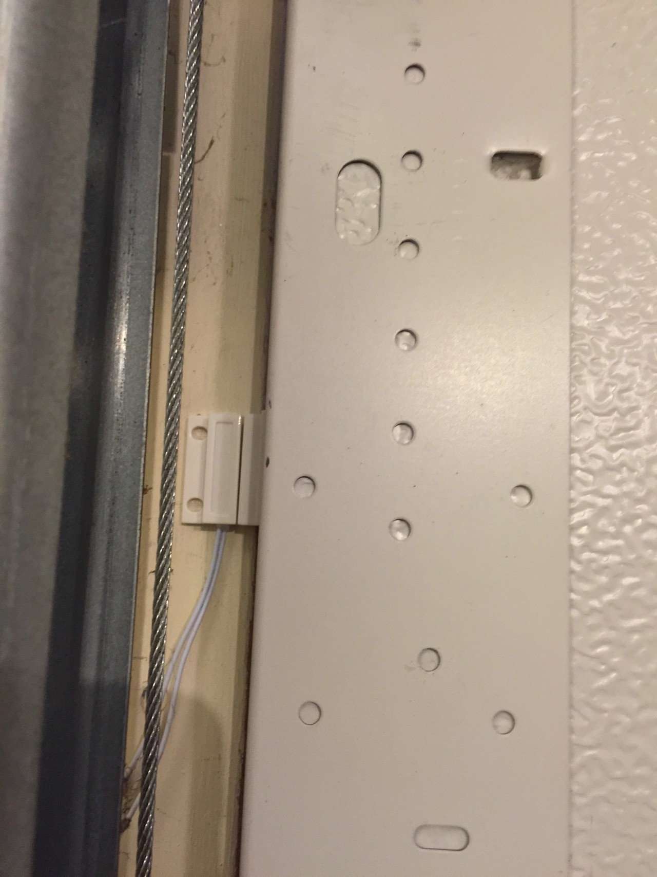
Connect the other two wires from the controller to a magnetic switch that is set up to close when the garage door is closed.
![]()
ESP8266 Wifi Smart Garage Door
Use an ESP-01 micro controller to control your Garage Door
 Pete Hoffswell


Discussions
Become a Hackaday.io Member
Create an account to leave a comment. Already have an account? Log In.
Hi Pete, thanks for sharing your project! I've been having fun experimenting with the ESP8266-01 modules so I thought I would try your example. Right now I'm having a problem installing the code on the ESP8266 so I wanted to ask if you might expand on that process a little more. I assume you made an init.lua file to go along with the code in your example? I'm sorry if this is a really basic question. I'm also having an issue with the relay energizing as soon as the module starts up. Perhaps that does not occur once the module is correctly programmed? Right now I have to disconnect both the relay and the switch from GPIO_0 and GPIO_2 before powering up the ESP8266 in order to connect with the module in ESplorer. Once its powered up and connected I can go ahead and connect the relay and switch and then everything works.
Are you sure? yes | no
Depending in the relay you are using it may be pulling GPIO0 LOW causing the ESP to boot into program mode.
Ohh I just read you comment without looking at the schematic. Probably not your issue but Just incase anyone is using GPIO0 to control a relay... watch for this.
Are you sure? yes | no