I've added circuit schematics and PCB layout files to the GitHub repository. Circuit is almost as simple as it could get. LEDs are connected to ATmega pins, with current limiting resistors. The encoder and the push-button are also connected directly to the µC pins, with pull-up resistors. All the LEDs, the push-button and the two encoder channels are each connected to its own dedicated pin. A 16MHz crystal, three capacitors, a programming header and another pull-up resistor complete the circuit.
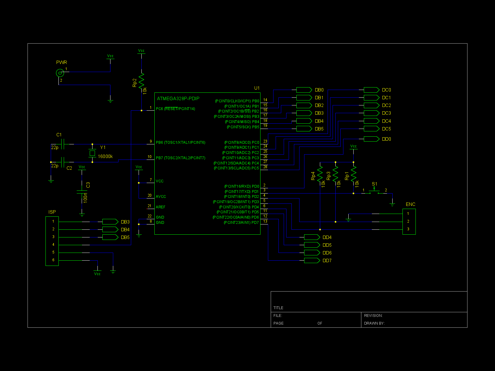
I used gEDA for schematic capture and the PCB layout. I'm a beginner with those and it took some time to learn it. But it was worth it.
MURB's precision as a clock depends on the crystal. One MURB I built advances about 4 seconds per day. This is a frequency error of about 50ppm. Maybe a different crystal would have better precision.
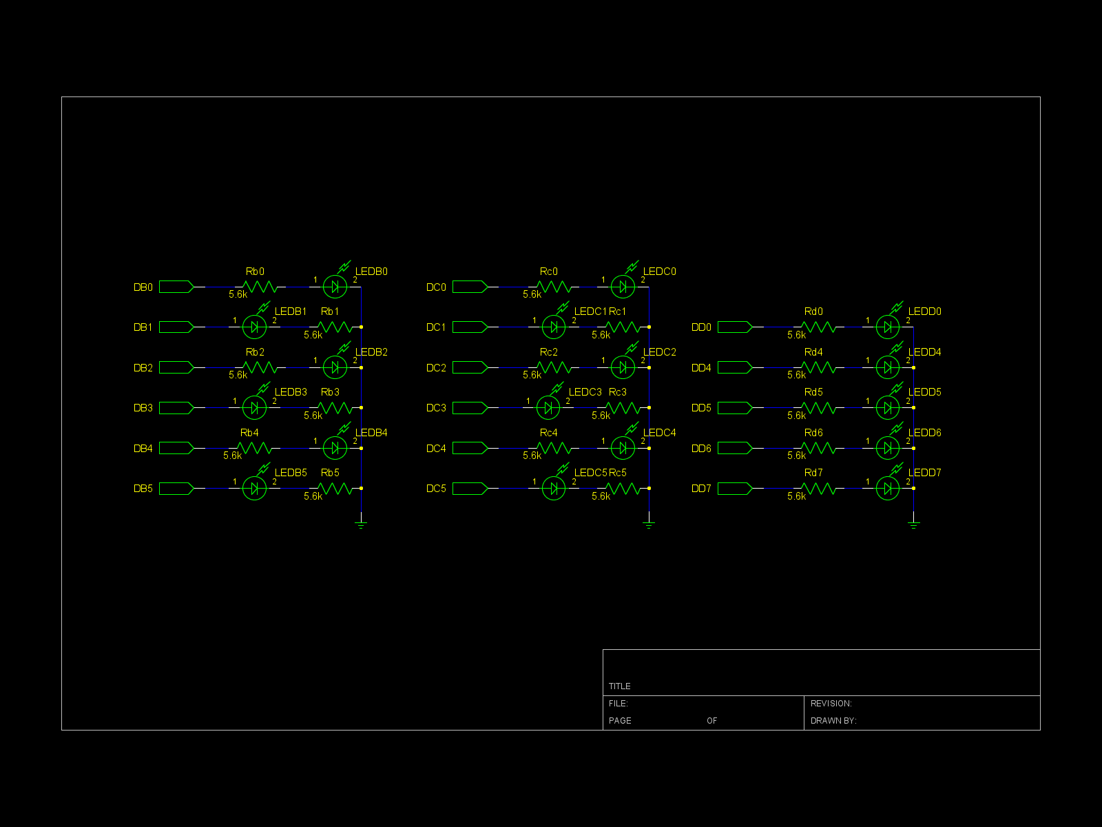
Another thing to note on the circuit above is the position of the resistors. Usually it doesn't matter much because they are in series with the LEDs. But since I'm using the schematic to create the PCB, I had to alternate the order LED-resistor in some pins to simplify the layout.
Discussions
Become a Hackaday.io Member
Create an account to leave a comment. Already have an account? Log In.