 Kevin Juszczyk
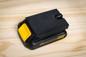
The Flexvolt battery incorporates a switch in the body of the battery which, in part, controls if the battery is wired up in series (60v) or parallel (20v.) The other piece of the puzzle is the connection between the C1 and C3 terminals. These are normally used for cell balancing during charging, but with the switch depressed, they can be connected together to produce 60v at the B+/- terminals. If the C1 and C3 terminals are connected without the switch depressed, two cells are shorted together which instantly bricks the battery (won't charge or run tools.)
The adapter body was printed in PLA with a 0.3mm layer height. The circuit board was milled on a Nomad 883 Pro CNC. Trace isolation, holes, and board cutout are all done with the same 0.025" regular length end mill. The middle terminals on the PCB should be cut down to half-height as shown using a dremel or file. The PCB can be screwed into the adapter body or glued, making sure that the PCB sits flush or just under the inside surface of the adapter body.
The middle two barrier block terminals are not connected to anything. They can be used to attach extra wires or components, if desired.
Note that the gerbers included with this project plot the bottom copper layer. If you are not using the Flatcam workflow(build.txt), then be sure to mirror both the gerber and excellon files 1" above the X axis. Alternatively, you can flip the layer in Kicad, move the C3 terminal to the other side of the C1 terminal, and then plot the top copper layer.
CAUTION:
The tools normally used with these batteries provide important protections against various adverse conditions. Thermal, over-current and discharge protections are bypassed with an adapter like this, so shorting the terminals, letting the battery get too hot or too deeply discharged will likely permanently damage it or worse.


 Vitor de Miranda Henrique
 ElectroBoy
 matteo
how do I buy one from you?