 Open Green Energy
keith.hungerford ( team member ) from Australia, who is one of the major contributor to this project.He has experimented a lot on this project.After my request he made this nice video explaining the efficiency,losses at various load,how DCM will take care at low load condition, about the MPPT v4 controller and writing of a new Arduino TimerOne library to handle our requirement.
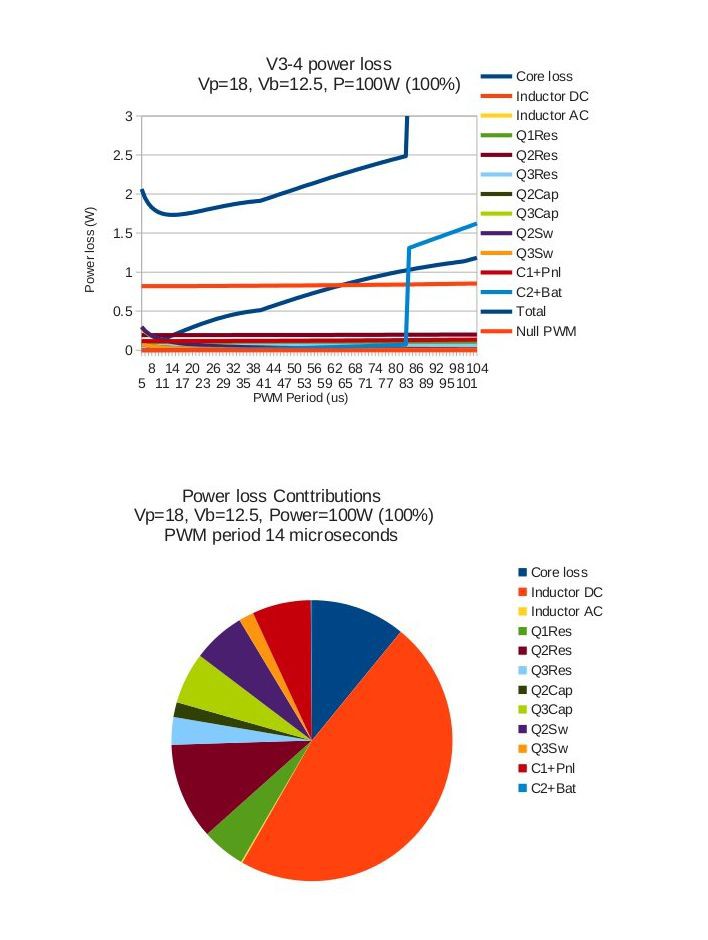
These are the loss analysis curves at different load condition.
At 100 Watt :
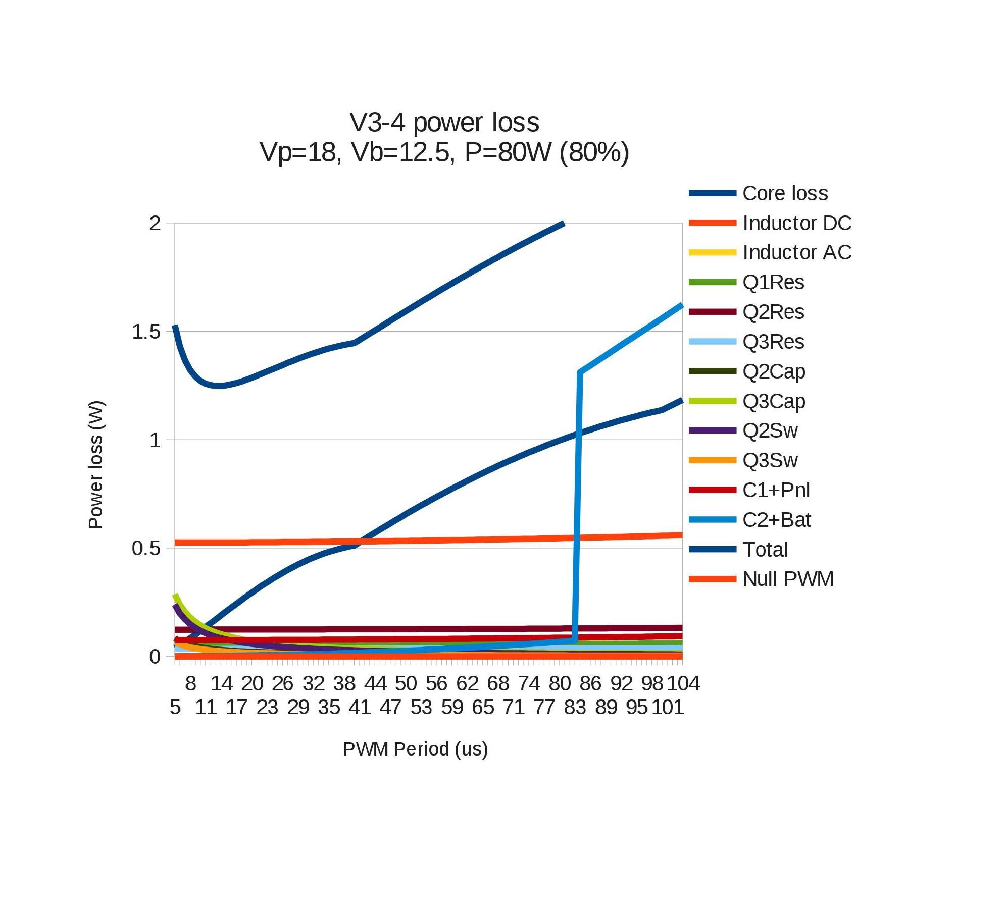
At 80 Watt :
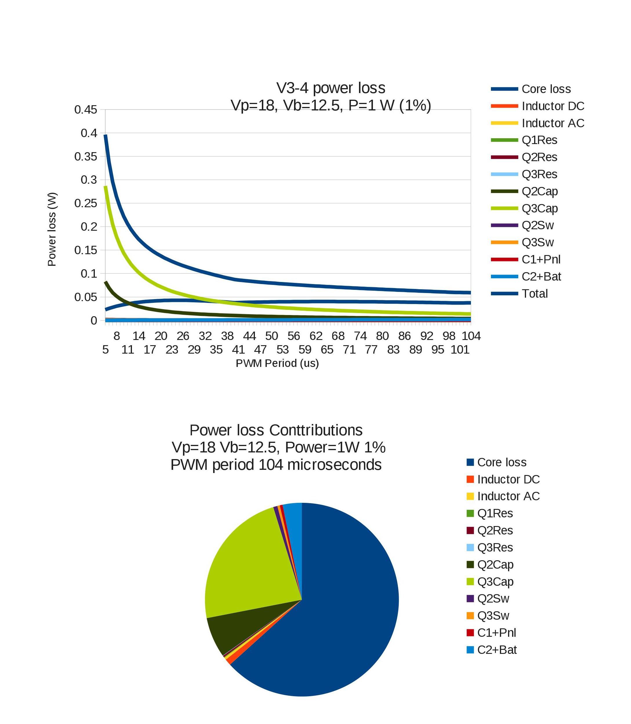
 At 1 watt :
In the 100% ( 100W ) graph, the optimum PWM period is 14 microseconds, at which period the decrease in the core loss is balanced by the increase in the switching and capacitive drive loss. When Keith checked, he found that the capacitive drive losses are so nearly equal to the switching losses that the curves fully overlap and you cannot see the capacitive loss curve. It is more clear at 80% ( 80W ) load where both curves are visible.
As the load decreases, the resistive losses decrease and the relative influence of these period-dependent losses increases, but the pattern remains the same. In the MOSFETS, the importance of the switching losses decreases with decreasing load, since there is less current flowing and therefore a reduced amount of charge to be absorbed, even though the voltage excursion is unchanged. The capacitive losses come to dominate. Because the switching losses are less, the optimum PWM period decreases with decreasing load. At 10% load it is down to 11 microseconds.
However the difference between the total loss at 11 microseconds and 14 microseconds is only 5% of the loss, so a single PWM period of around 14 microseconds is quite efficient SO LONG AS THE CONTROLLER IS IN CCM.
Somewhere below the 10 % load point, but above the 5% load point, the controller goes into DCM. That is, there is not enough current flowing out of the panel to make the current in the inductor always flow in the same direction.
His design assumption in this spreadsheet is that the controller algorithms explicitly support DCM. That is, they switch off Q3 at the time that the current would start flowing "backwards". So now, in DCM, the controller has 3 phases within the PWM period. There is the phase when current flows from the panel via Q2 through the inductor, and increases. there is the phase when current flows from Earth via Q3 through the inductor, and decrease. Then there is the Null phase when no current flows through the inductor.
This Null phase is a good one as far as losses in the inductor and MOSFETs are concerned - there is no current and so no loss. However C1 is receiving all of the current from the panels, and C2 is delivering all of the current to the battery or load. This creates extra voltage ripple at the panels, and at the battery/load.
So long as the voltage ripple at the panels and battery/load is within reasonable limits, in DCM it is better to have a much longer PWM period. Hence the appearance of very long PWM periods at very low load levels. The length of the PWM period is mainly limited by the voltage ripple tolerable at the battery, and the reduction in efficiency of the panel caused by the ripple there.
Discussions
Become a Hackaday.io Member
Create an account to leave a comment. Already have an account? Log In.