 Andrew Retallack
The T-Board was designed with the following in mind:
- Speed: Allow microcontroller prototyping on a breadboard, simply and quickly
- Ratsnest: Reduce the number of wires needed to prototype with microcontrollers
- Power: Allow the project to be easily self-powered, at either 5v or 3v3
- Programmable: Easily program using FTDI modules (for the ATmega328), or ICSP programmers
- Flexibility: Choose your own Crystal, so that you can experiment with low-power modes.

 DIY GUY Chris
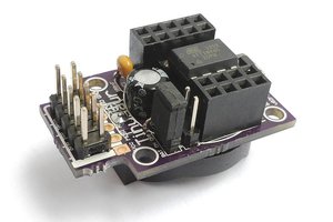
 Neven Boyanov
 danjovic
 Alex Martin
The T-Board has evolved into the Toadstool. Check it out here:
https://hackaday.io/project/4234-the-toadstool